System and Method for Predicting Radon Mitigation Fan Failure Using Motor Current Signature Analysis, Suction Pressure Telemetry, and Acoustic Bearing Analysis with Radon Trend Corroboration
A radon fan runs 8,760 hours a year, and the only warning device most homes have is a plastic tube of colored liquid that nobody checks. When the fan dies, radon climbs back toward the level that sent the family to mitigation in the first place, and the house stays silent about it for months.
Abstract
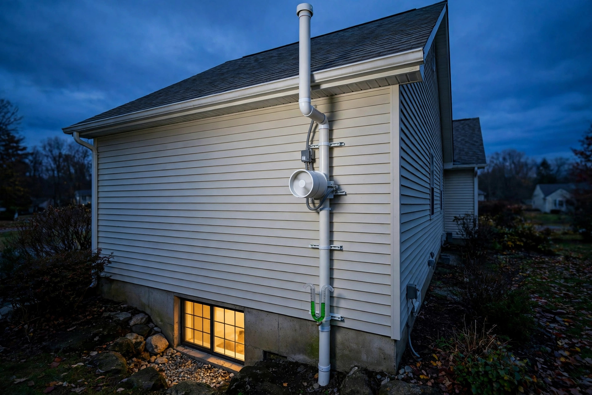
Radon is the second leading cause of lung cancer in the United States, and the standard fix is a small fan that runs forever. An active soil depressurization system pulls air from beneath the foundation slab and vents it above the roofline, holding indoor radon below the U.S. Environmental Protection Agency (EPA) action level of 4 picocuries per liter. Of every part in the system, the fan alone moves. It runs 8,760 hours a year, and it typically lasts five to ten years. When it fails, nothing in the house announces it. When the fan dies, the U-tube manometer on the vent pipe goes level, the low hum stops, and indoor radon begins a slow climb back to its unmitigated level. EPA guidance says to retest every two years, so a fan that dies the month after a clear test can expose a household for up to two years before anyone measures radon again. This disclosure gives the fan a voice before it goes silent.
Disclosed is a system and method for predicting failure of a radon mitigation fan before the fan stops moving air, using four channels that are already measurable at the fan and the pipe. Current is read by a split-core current transformer on the fan supply, and motor current signature analysis extracts bearing defect frequencies, rotor sidebands, and capacitor degradation from the spectrum, with the single-phase corrections described in section 2. Suction is measured by a digital differential pressure sensor tapped at the manometer port, continuously, and compared against a learned suction-versus-current fan curve that, as an empirical pattern rather than a deduced rule, separates a dying fan from a leaking slab and from a blocked stack. Sound is tracked by a micro-electromechanical systems (MEMS) microphone or accelerometer on the fan housing, following blade-pass tones and bearing noise through envelope analysis. In the lowest occupied level, a continuous radon monitor provides a slow corroborating channel: a rising radon trend corroborates a mechanical diagnosis, while a flat radon trend does not yet confirm it. The disclosure gates a Replace Soon tier, and a Failed tier reached by score, on radon agreement or agreement between two mechanical channels, which is the binding form of the corroboration, and an acoustic-only score is capped at Watch under section 6; that gating is background, not part of the claimed combination.
Four channels combine into a health score with four tiers by a linear weighted sum, and a failure-mode classifier maps channel patterns to root causes, the claimed mapping covering only the gate-governed bearing-wear, capacitor-degradation, and gate-open generic weakening patterns, with the gate-open generic diagnosis of an unclassified weakening fan as the gate's fallback (section 7). The claimed combination is the quadrant-plus-spectral-gate disambiguation of section 3, not the fusion itself. Replacement is scheduled while the fan still runs, not after radon has already climbed, within an illustrative six-week window that has no demonstrated lead time behind it.
No new sensor needs inventing. Split-core current transformers cost a few dollars, MEMS microphones are in every phone, differential pressure sensors are commodity parts, and continuous radon monitors report hourly readings where installed. What does not exist is the system that applies the quadrant-plus-spectral-gate disambiguation to a radon fan and says, in plain language, that the fan is wearing out.
- 21,000 lung cancer deaths a year in the United States attributed to radon by the EPA, the second leading cause after smoking and the leading cause among people who never smoked, about 2,900 of them in never-smokers (refs 1, 2).
- 4 pCi/L is the EPA action level for indoor radon (148 becquerels per cubic metre, Bq/m3, the exact conversion; the EPA page prints the rounded 150 Bq/m3), with no known safe level, and the EPA recommends considering mitigation between 2 and 4 pCi/L; the average American home measures about 1.3 pCi/L and outdoor air about 0.4 pCi/L (ref 1).
- 7 in 1,000 is the EPA lifetime lung cancer risk for a never-smoker living at 4 pCi/L, against about 62 in 1,000 for a current smoker at the same level (ref 2).
- 8,760 hours a year a radon fan runs, because the EPA says the fan should never be turned off (ref 25), which is 43,800 to 87,600 hours over a typical five to ten year service life.
- 12 months is RadonAway's base warranty on its RP series fans, from purchase, or 18 months from manufacture, extended to 5 years from purchase or 66 months from manufacture only with professional installation (ref 4); a mitigator's summary reports Fantech lists five years on its Rn radon fans (ref 8).
- 34 to 66 watts is what a RadonAway RP145 draws per its 2025 manual (ref 4), moving 169 cubic feet per minute at zero static pressure, 150 at 0.2, 124 at 0.5, 101 at 0.75, 81 at 1.0, 61 at 1.25, 42 at 1.5, 22 at 1.75, and 4 at 2.0 inches of water column, with a maximum recommended operating pressure of 1.7 inches of water column. An earlier RP145 revision was rated 41 to 72 watts per a RadonAway fan flyer (ref 5).
- 0.5 to 1.75 inches of water column is the typical U-tube manometer reading on a working system (ref 7), and a level reading means the suction is gone.
- 2 years is the EPA retest recommendation for a home with a mitigation system (ref 25), reflected in the SGM-SF-2023 label guidance (ref 17), which is the longest a dead fan can hide between measurements.
- 42% of induction motor faults are bearing faults, per Institute of Electrical and Electronics Engineers (IEEE) data cited by Shukla and colleagues (ref 10), and the transfer to a 34 to 66 watt fan is unvalidated (see Background).
For a homeowner reading this: go look at the U-tube manometer on your radon pipe once a month. If the two liquid columns are level, your fan is dead or your power is out, and you should call your mitigator now, not at the next retest. If the reading has drifted well below the mark your installer left on the label, something has changed even though the fan still hums. A new grinding or whining sound from the fan is a bearing telling you to call your mitigator promptly. None of these checks needs a tool. All of them need remembering, which is why a fan that can report on itself is worth building.
Field of the Invention
This invention relates to residential building health and predictive maintenance: continuous prognostics for radon mitigation fans in active soil depressurization systems, in which a learned suction-versus-current quadrant checked against a current-spectrum gate disambiguates a weakening fan from a slab leak, supported by motor current signature analysis, suction telemetry, and acoustic bearing analysis, with radon trend corroboration as background to the claimed combination.
Background
Radon reaches a house from the ground, not from the air. Uranium in soil and rock decays to radium, radium decays to radon gas, and radon, being a gas, moves through soil pores toward any opening. A house sits on that soil with a pressure difference working against it: warm indoor air rises and escapes through the upper envelope, which pulls replacement air in through the lowest openings, a stack effect that depressurizes the basement and slab by a few pascals relative to the soil. Soil gas follows the pressure gradient through foundation cracks, slab joints, sump pits, and utility penetrations. Outdoor air averages about 0.4 pCi/L. Across the United States, the average home averages about 1.3 pCi/L. Homes over high-radon geology measure far more, and the EPA action level of 4 pCi/L marks where the agency recommends fixing the home, while stating plainly that no level is known to be safe. Globally, the World Health Organization recommends a reference level of 100 Bq/m3, about 2.7 pCi/L, lower than the EPA action level (ref 16).
Active soil depressurization reverses the gradient (ref 3). A suction point is cut through the slab into the gravel bed beneath, a polyvinyl chloride (PVC) pipe runs from that point up through the house or along its exterior to above the roofline, and an inline centrifugal fan in the pipe pulls soil gas out from under the slab and vents it outdoors. By holding the sub-slab region at a lower pressure than the living space, the fan makes air flow down through the slab cracks instead of up into the house. EPA guidance reports that some radon reduction systems can reduce radon levels by up to 99 percent (ref 25). At 34 to 66 watts and 5.5 pounds, a RadonAway RP145 is small. Everything else in the system is pipe and sealant.
That simplicity is the failure mode. A fan has one way to fail that matters, and it fails the way small induction motors fail: bearings wear, the run capacitor dries out, the impeller fouls with dust and condensate, or the motor stops after tens of thousands of hours of continuous duty. EPA guidance says the fan should never be turned off, so a five year old fan has already run about 43,800 hours, and a ten year old fan about 87,600. RadonAway's warranty tells the same story in contract form: 12 months from purchase or 18 months from manufacture as the base term, extended to five years from purchase or 66 months from manufacture only when a professional installs the fan. Anything beyond the warranty is luck; the warranty itself is the honest number.
What a homeowner gets as a warning system is a U-tube manometer, a plastic U filled with colored liquid, tapped into the vent pipe (ref 6). When the fan pulls suction, the liquid column on the pipe side sits higher than the column open to the room, and the difference reads out in inches of water column, typically 0.5 to 1.75 on a working system (ref 7). When the fan dies, the columns level out. Some systems add a status light or an audible alarm wired to a pressure switch. American National Standards Institute / American Association of Radon Scientists and Technologists (ANSI/AARST) Soil Gas Mitigation Standards for Existing Homes, SGM-SF-2023 (ref 17), the current standard, requires active notification of a fan failure, yet the device is a gauge that only works if someone walks over and looks at it, or a pressure alarm that sounds after the fan has already died. EPA guidance says to check the warning device regularly and retest radon at least every two years (ref 25). Between tests, the house has no radon sensor, no fan sensor, and no one watching either one. A fan that dies in January after a clear test in December can expose a household until the next scheduled retest, up to two years later, and the exposure is invisible because radon has no smell, no color, and no immediate symptom.
Motor current signature analysis is the established way to watch a motor without touching it, and it has been used on large industrial induction motors for decades. A healthy motor draws a clean sinusoidal current at the supply frequency. A mechanical or electrical fault disturbs the magnetic field and writes sidebands into the current spectrum at frequencies predicted by the fault physics. Broken rotor bars produce sidebands at (1 ± 2s)f1, where s is the slip and f1 is the supply frequency. Bearing defects modulate the air gap and produce sidebands around the supply frequency at f_s ± k·f_C, where f_s is the supply frequency, f_C is the bearing defect frequency, and k is the harmonic order, capped so no searched frequency exceeds the 1 kHz detection band. BPFO, the outer-race frequency, is about 0.4 times the ball count times the rotor mechanical frequency, and BPFI, the inner-race frequency, is about 0.6 times the ball count times the rotor mechanical frequency, the 0.4 and 0.6 factors being the values stated in ref 12.
With six to twelve balls and a rotor at the series nameplate 3000 revolutions per minute, 50 revolutions per second (ref 4), the defect frequencies themselves fall roughly between 120 and 360 Hz. In the current spectrum the usable sidebands are the upper ones at 60 Hz plus those frequencies, 180 to 420 Hz, and the folded lower sidebands at the magnitude of 60 Hz minus the defect frequency, 60 to 300 Hz. At the six-ball end of the range, the lower sideband of the BPFO defect frequency lands exactly on the 60 Hz fundamental and is unusable, and the lower sideband of the BPFI defect frequency lands on the 120 Hz torque-pulsation component and is likewise unusable, masked by the torque-pulsation, so the search excludes 5 Hz around 60 Hz and around 120 Hz. For seven to twelve balls the folded sidebands fall at 80 to 180 Hz for BPFO and 150 to 300 Hz for BPFI and remain usable outside the exclusions. In vibration and acoustics the defect frequencies appear directly.
About 42 percent of induction motor faults are bearing faults, per IEEE data cited by Shukla and colleagues.
Single-phase capacitor-run motors have now been tested with this technique in the laboratory. Al-Yoonus and Alyozbaky (ref 9) showed in 2021 that the input current waveform of a single-phase induction capacitor-run motor reveals broken rotor bars, bearing faults, and the effect of varying the run capacitor value on the wave shape and on total harmonic distortion, using a microcontroller to record the current and MATLAB to analyze it. Shukla and colleagues (ref 10) showed in 2025 that a Raspberry Pi with a current sensor, a triaxial accelerometer, a temperature sensor, and a voltage sensor can classify five single-phase motor conditions, front-end bearing fault, winding short circuit, open capacitor fault, undervoltage, and normal operation, at 98.5 percent accuracy with a random forest model. Liu and colleagues (ref 11) showed in 2019 that fusing vibration and current signatures diagnoses induction machine faults better than either signal alone. None of these studies ran on a radon fan. Shukla's motor was a bench motor under laboratory fault conditions, Al-Yoonus and Alyozbaky tested a laboratory capacitor-run motor, and Liu's machines were three-phase industrial motors. No published study has demonstrated current signature analysis on a fractional-horsepower single-phase radon fan running continuously in a house, and the transfer is not free. A 34 to 66 watt fan draws about 0.28 to 0.55 amps at 120 volts at unity power factor, and about 0.35 to 0.79 amps at the typical power factor of a small single-phase induction motor, 0.7 to 0.8. A sideband 45 dB below the fundamental is about 2.0 to 4.4 milliamps. Resolving it needs a low-range current transformer, a 16-bit converter, and coherent averaging, not a whole-house clamp.
Failure alarms for radon fans already exist, and they define the boundary of what this disclosure adds. RadonAway's Air Flow Alarm (ref 13) watches a vane in the vent pipe and sounds a buzzer when airflow drops below a critical level. Tjernlund's RA1 (ref 14) measures system exhaust pressure directly; a roundup of fan-failure monitors reports that direct pressure measurement catches a partially iced pipe termination that a vane can miss. RadonAway's RSA1 (ref 15) monitors vacuum with a piezoresistive pressure sensor and meets the standard's active notification requirement. All three detect a fan that has already failed. None of them warns of wear before the fan dies, none combines a suction-versus-current quadrant with a current-spectrum gate, and none names the root cause. Two distinctions are worth stating, because they are where this disclosure differs from the nearest prior work.
First, Al-Yoonus and Alyozbaky (ref 9), Shukla and colleagues (ref 10), and Liu and colleagues (ref 11) all diagnose motor faults from current and vibration, but none applies the diagnosis to a radon mitigation fan, none reads the suction-versus-current fan curve, and none corroborates the diagnosis against an indoor radon trend. Resolution is the technical problem the combination addresses: resolving that sideband on a fan that runs continuously and almost never starts. Second, the radon alarms detect the absence of airflow or pressure, which is a binary post-failure signal, while this disclosure scores gradual degradation across four channels and classifies the failure mode before the fan stops; the claimed contribution is the quadrant-plus-spectral-gate disambiguation, not the four-channel scoring itself. A person applying refs 9 to 11 to the radon-fan problem would still lack the combination. Refs 13 to 15 sense pressure or airflow only, with no current measurement, so they cannot supply the suction-versus-current quadrant; refs 9 to 11 diagnose motors from current and vibration but never read a fan curve, never learn a per-installation operating point, and never corroborate against a radon trend; and none of them addresses the resolution problem of a 2.0 to 4.4 milliamp sideband on a fan that draws under an amp. Quadrant-plus-spectral-gate disambiguation of a weakening fan from a slab leak is the claimed combination; the fusion itself is a linear weighted sum with no cross-channel interaction term, and the discordance hold, the holding of channel scores at zero until their persistence requirements are met, and radon corroboration are generic gating and background.
Adjacent disclosures in this series cover parts of this ground. LITF-PA-2026-022 (ref 18) estimates indoor radon continuously from barometric pressure and a physics-informed model, but it measures radon, not the hardware that controls it. Motor current gives sump pump health in LITF-PA-2026-138 (ref 19), the same sensing idea applied to a different pump with an intermittent duty cycle and a different failure consequence. Well pumps are diagnosed from current-cycle timing and tank drawdown in LITF-PA-2026-166 (ref 20), but it contains no centrifugal fan curve and no suction-versus-current reasoning. LITF-PA-2026-116 (ref 21) estimates compressor remaining useful life from current harmonics, the closest analog in the series, but it watches a larger hermetic compressor, a single-phase permanent split capacitor (PSC) or scroll machine, with different failure physics and no pressure or radon channel. A standby generator is watched through its weekly exercise cycles in LITF-PA-2026-196 (ref 22), an intermittent-duty problem, while a radon fan runs continuously and never gets a weekly test run. LITF-PA-2026-201 (ref 23) quantifies water heater sediment from passive acoustics, an acoustic measurement of a static deposit, not a rotating machine. LITF-PA-2026-231 (ref 24) detects furnace heat exchanger cracks from flame disturbance and combustion acoustics, a combustion failure mode with no motor, no fan curve, and no radon channel. No disclosure in the series watches a radon mitigation fan, applies a quadrant-plus-spectral-gate disambiguation to one, or classifies the failure mode before the fan stops.
What is missing is the quadrant-plus-spectral-gate disambiguation applied to a radon fan: the learned suction-versus-current quadrants checked against the current spectrum, with the acoustic bearing channel and the radon trend as corroboration, built from commodity sensors and established motor diagnostics adapted to a small single-phase motor, with the transfer gap stated openly.
Detailed Description
1. System Architecture
Two parts make up the system, a sensing node at the fan and a fusion service that can run on a hub in the house or in the cloud, plus an optional radon monitor in the lowest occupied level. Clamped onto the fan circuit and the vent pipe, the sensing node needs no modification to the fan or the pipe beyond a pressure tap at the existing manometer port. It reports four channel scores and a health tier, and it keeps reporting even when the radon monitor is absent, with the radon channel excluded and the remaining weights renormalized. All numeric thresholds, weights, action levels, and timing values in this disclosure are estimates unless stated otherwise.
Inside the node, five sensors share one board. Clipped around the fan supply conductor, a split-core current transformer, SCT-013-005 class with a 5 amp range and a built-in burden giving 0 to 1 volt output, reads the motor current waveform. It feeds a fixed times-ten gain stage and then a 16-bit successive-approximation converter, ADS8866 class with a 5 volt reference, sampling at 12 kHz behind a second-order Butterworth Sallen-Key anti-alias filter at 1.2 kHz. With a 6 kHz Nyquist limit, the 1 kHz band edge sits inside the passband. Fifty hertz to 1 kHz is the current transformer bandwidth, and it bounds the detection band, while content above 1 kHz is attenuated, about 28 dB at the 6 kHz Nyquist and about 38 dB at 11 kHz for the Butterworth response, rather than absent.
At 1 kHz, the 1.2 kHz Butterworth attenuates by about 1.7 dB and the 960 Hz harmonic by about 1.5 dB, biasing the measured total harmonic distortion low. Through the same chain, the learned baseline total harmonic distortion is measured, so the attenuation approximately cancels in the total harmonic distortion ratio. Cancellation is exact only if the harmonic distribution is unchanged as the capacitor degrades, since the attenuation rises with frequency from about 0 dB at 120 Hz to about 1.5 dB at 960 Hz. The worst in-band case is an 11 kHz spur folding to the 1 kHz band edge, attenuated about 38 dB, which is marginal for a minus 45 dB detection, since aliased spurs fold in only about 38 dB down at worst case in band, so the detection relies on the current transformer rolloff above 1 kHz as well. An isolated voltage transformer module, ZMPT101B class, samples the fan supply voltage on the unswitched line side of the relay at the same 12 kHz for phase reference and supply sag detection. Below 108 volts root mean square (RMS) for longer than one second, an estimated threshold, a supply sag is declared; sags are logged as diagnostic only and enter no score, because a brownout moves all three mechanical channels at once and is not a fan fault.
Each 1 Hz RMS sample is the RMS voltage over the preceding 1 second, computed once per second. Sag detection reads the live 1 Hz RMS stream directly, not the one-minute means, and a sag is counted when two consecutive 1 Hz RMS samples fall below 108 volts, which means the 1 second RMS voltage was below 108 volts in each of two consecutive seconds, longer than the 1 second sag duration; the 1 Hz RMS stream runs continuously, including during the 6-hourly spectral captures, so zero-current and sag detection are never blind. From the first 1 Hz RMS sample below 108 volts until the first 1 Hz RMS sample at or above 108 volts, a sag is active; a single-sample dip below 108 volts is active for that sample but is not counted as a sag.
Total harmonic distortion is measured on the current waveform as the ratio, expressed as a percentage, of the root-sum-square of harmonics 2 through 16 relative to the 60 Hz fundamental, computed on every 6-hour current capture, so the highest harmonic measured is 960 Hz, inside the 0 to 1 kHz detection band.
A digital differential pressure sensor, 0 to 2 inches of water column range with 0.01 inch resolution and an Inter-Integrated Circuit (I2C) interface, SDP800 series class, connects to the manometer port through a T-fitting and samples vent-pipe suction once per second. RMS current and RMS voltage are sampled at 1 Hz continuously, including during the 6-hourly spectral captures, and one-minute means are derived from the 1 Hz stream; the fan-curve fit and the pressure channel consume the one-minute means, while the zero-current response and the sag detection read the live 1 Hz stream directly. On the fan housing within 10 centimeters of the motor end bell mounts a digital Inter-IC Sound (I2S) MEMS microphone, ICS-43434 class with minus 26 decibels relative to full scale (dBFS) sensitivity. For a fan outdoors in weather, a MEMS accelerometer, ADXL355 class, three-axis, plus or minus 2 g range, bonds to the housing instead, sampled at 16 kHz with a bandwidth covering the blade-pass frequency and the 2 to 4 kHz envelope band. Its acceleration signal is converted to the same dBFS broadband and tone features by the envelope pipeline of section 4, as 20 times log base 10 of acceleration over the plus or minus 2 g full-scale acceleration, calibrated at install so its noise floor maps to the microphone's dBFS noise floor. The same install acoustic function check verifies it by listening for the blade-pass vibration with the fan running. On the fan housing, a temperature sensor records motor case temperature as a learning covariate and triggers a thermal alert above 75 degrees Celsius.
The thermal alert is diagnostic only and enters no score; it notifies the homeowner and mitigator directly. Outdoor temperature, barometric pressure, and precipitation rate, which sections 3, 4, and 5 consume, come from the hub weather feed, a local weather station where the house has one and otherwise a weather service, since the node itself carries no outdoor sensor. Indoor barometric pressure comes from a barometric pressure sensor on the hub, BME280 class; where the hub has no barometer the radon channel is excluded from the fusion until one is connected, since the foundation pressure differential needs it. Without the hub weather feed, the radon channel is excluded from the fusion until the feed returns, since weather normalization needs it, and the remaining channels score on with renormalized weights and thresholds. Indoor temperature and heating, ventilation, and air conditioning (HVAC) state, which the radon model consumes, come from the hub. Indoor temperature comes from the home automation system where one is connected, otherwise from a dedicated indoor temperature sensor on the hub. In a cloud deployment with no hub sensor and no home automation connection, indoor temperature is unavailable and the radon channel is excluded from the fusion until a source is connected. HVAC state, one of off, heating, cooling, or fan-only circulation as reported by the thermostat, comes from the thermostat where one is connected, otherwise assumed off and flagged as an assumed input, and any other mode the thermostat reports, such as dehumidify or auxiliary heat, is treated as unknown and falls to the section 5 default.
With HVAC state assumed, the radon channel is excluded from the fusion until the state is known, since an assumed HVAC state is a systematic error in the model prediction, not random noise; radon agreement is therefore unavailable and the discordance rule requires two mechanical channels. Powered from the fan circuit through an isolated AC-DC module, the node draws under 2 watts and reports over Wi-Fi, Thread, or a wired connection to the hub. A relay in series with the fan, with the node powered from the unswitched line side of the circuit, lets the node interrupt the fan for the weekly restart of section 2.
Installation takes one visit and no new wiring. Around the fan supply conductor inside the junction box clips the current transformer, the pressure sensor tees into the manometer port, the microphone adheres to the fan housing with a magnetic or adhesive mount, and the node plugs into the same outlet as the fan. On first power-up the node enters a 30 day learning period, during which it records the fan baseline: the current spectrum, the suction and current pairs across the range of outdoor temperatures and barometric pressures the house experiences, the acoustic signature, and the case temperature. Learned baselines replace fixed thresholds after the learning period, because every installation has a different operating point on the fan curve and a different acoustic environment. Baseline populations are: the current, rotor, bearing, and total harmonic distortion baselines are the 30-day median over all 6-hourly captures, and the acoustic broadband and tone baselines are the 30-day median over dry-weather hourly captures only. Installed on a replacement fan, a node re-learns from the new fan, and the old baseline is kept as a record of how the previous fan died. During the 30 day learning period no tier or diagnosis is reported; the system reports a learning status, and the zero-current and zero-suction Failed overrides still apply. In a region with an existing fleet, a new installation computes scores from day 1 on the regional set as its initial thresholds, but reports no tier or diagnosis until Step 3 acceptance, when it switches to its own learned baselines; the regional set provides initial thresholds for score computation, not for tier reporting.
One rule governs missing channels throughout the system. Any channel that is unavailable, a radon monitor that was never installed, a microphone saturated by heavy rain, a pressure sensor under service, is excluded from the fusion, and the remaining channel weights are renormalized to sum to 1, and the tier thresholds are scaled by the same factor, so the tier thresholds track the renormalized weights, though a score exactly at a threshold can change tier when a channel is absent. With no radon monitor installed, the health score is H = (0.35 × M + 0.30 × P + 0.20 × A) / 0.85, with thresholds Healthy below 0.353, Watch from 0.353 to below 0.647, Replace Soon from 0.647 to below 0.882, and Failed at 0.882 and above, with M, P, A, and R defined in sections 2, 3, 4, and 5. No channel ever defaults to a numeric value that silently shifts the score.
2. Motor Current Signature Channel
Current and acoustics are two views of the same wear, and the fusion does not depend on which one fires first. Bearing wear is typically gradual rather than sudden, an assumption stated here and not a measured result (see Limitations), and the wear writes itself into the current spectrum and into the sound before the suction drops enough to notice on the manometer. Which channel sees it first varies by failure, so the disclosure claims no ordering between them.
Every 6 hours, at 00:00, 06:00, 12:00, and 18:00 local time, the node captures sixteen 10-second records of current at 12 kHz, applies a Hann window to each, and computes the spectrum from 0 to 1 kHz. Each 120,000-sample record is zero-padded to 131,072 points, giving 0.092 Hz bin spacing, and the sixteen records are averaged coherently after alignment to the mains zero crossing: each record starts at a rising mains zero crossing detected from the voltage channel, and is resampled by linear interpolation to an integer number of mains cycles before time-domain averaging. For the alignment, the voltage channel provides the mains zero-crossing phase reference. All decibel figures in this section are relative to the 60 Hz fundamental amplitude. Three fault families are extracted, each with a clamp formula that maps the measured deviation to a 0 to 1 sub-score, and the channel score M is the maximum of the sub-scores. Rotor bar and eccentricity faults appear as sidebands at (1 ± 2s)f1 around the 60 Hz fundamental, where s is the slip.
Slip is measured directly from the spacing between a sideband and the fundamental, which equals 2·s·f1, while the spacing between the two sidebands is twice that, 4·s·f1. It searches a band of the predicted frequency plus or minus 10 percent, with a minimum half-width of 5 Hz, both estimated, around the predicted frequencies rather than at a single exact frequency. A sideband counts as persistent only when it appears in three consecutive captures, the same three-capture count the channel persistence rule of section 3 uses. Each capture computes the sub-score; it is not held back until three captures accumulate. Persistence gates the release of the channel score, not the computation of the sub-score. Rotor mechanical frequency comes from the motor nameplate rating. Continuous Duty 3000 revolutions per minute, 50 revolutions per second, is the RP/XP Pro Series rating (ref 4), a series-level rating, against the 3600 revolutions per minute synchronous speed of a two-pole 60 Hz motor, so slip at the rated operating point is about 16.7 percent.
Ten to 20 percent is the slip search range, a sideband spacing of 12 to 24 Hz from the fundamental, with the exact slip measured from the sideband spacing itself. Excluded from the search is 5 Hz around the 60 Hz fundamental. M_rotor, the rotor sub-score, is clamp((sideband_dB minus baseline_dB) / (action_dB minus baseline_dB), 0, 1), where sideband_dB is the largest upper slip-sideband peak in the search band, in dB relative to the fundamental. Since the lower sideband at 36 to 48 Hz falls below the current transformer 50 Hz lower edge, it is not used, so detection relies on the upper sideband. Baseline_dB is the effective baseline, the 30 day median sideband level learned for the installed fan during the 30 day baseline, capped at minus 35 dB, that is, the lesser of the learned level and minus 35 dB. Action_dB is the rotor action level, computed from the effective baseline: the action level is the greater of minus 35 dB and the effective baseline plus 5 dB, so the action level is always at least 5 dB above the effective baseline and always scores 1.0.
With the learned baseline 1 dB below minus 35 dB, the action level is minus 31 dB, so a sideband at minus 35 dB scores 0.20, not 1.0, and the rotor term reaches 1.0 when the sideband reaches the action level, which is a rise of at least 5 dB above the effective baseline in every case.
For a learned baseline at or above minus 35 dB, the effective baseline is minus 35 dB, the cap, and the action level is recomputed from the effective baseline, so the sub-score is still computed with no cliff between a baseline just below and just above minus 35 dB. For example, a learned baseline of minus 34 dB is capped to minus 35 dB, giving an action level of minus 30 dB, and a sideband at minus 32 dB scores 0.60. Only when the sideband reaches the recomputed action level does the high-baseline fault fire, not merely because the baseline is high.
Bearing defects appear as sidebands around the supply frequency at 60 Hz plus or minus the bearing defect frequency and its harmonics, f_E = f_s ± k·f_C, where f_C is the defect frequency and k is 1 or 2; the second harmonics extend the upper sidebands to 780 Hz and the folded lower sidebands to 660 Hz, all inside the band. BPFO and BPFI, the outer-race and inner-race frequencies defined in Background, fall roughly between 120 and 360 Hz for six to twelve balls at the nameplate speed. Current-spectrum search covers the upper sidebands at 60 Hz plus those frequencies, 180 to 420 Hz, and the folded lower sidebands at the magnitude of 60 Hz minus the defect frequency, 60 to 300 Hz, excluding 5 Hz around 60 Hz and around 120 Hz, both estimated exclusions. These exclusions apply because the BPFO lower sideband lands exactly on the 60 Hz fundamental and is unusable and the BPFI lower sideband lands on the 120 Hz torque-pulsation component. Plus or minus 10 percent, with a minimum half-width of 5 Hz, is the search band around each predicted frequency. From the fan geometry or from the learned baseline, the exact frequencies are refined: the refined frequency is the frequency of the largest counted peak within the search band around the predicted frequency. Ball count for the installed fan is learned from the acoustic envelope spectrum during the 30 day baseline and stored as a learned parameter, with the motor service data used only as a starting guess where available, because the claimed limitation is the learned route, not a nameplate lookup.
Learning uses the 30 day median of the hourly 5 second envelope spectra from dry-weather captures only, dry weather as defined in section 4, the spectra computed with a default resonance band centered at 3 kHz with the same 500 Hz bandwidth as the sweep, before the sweep refines it. It searches for peaks in the 120 to 360 Hz defect domain. For each candidate ball count from six to twelve, it scores the count by the summed prominence of envelope peaks within 5 Hz of the predicted BPFO and BPFI frequencies and their second harmonics. Prominence is the height of the largest envelope peak within 5 Hz of a predicted frequency above the envelope noise floor. Only when its prominence is at least 6 dB above the envelope noise floor, the prominence threshold, does a peak count. With no counted peak, a predicted frequency contributes zero.
During candidate scoring the envelope noise floor is the median level across the 120 to 720 Hz range with no exclusions, since the ball count is not yet known; the exclusions apply only after the count is learned. Only when at least two of its predicted frequencies have counted peaks, each counted peak having prominence of at least 6 dB, is the highest-scoring count stored, with ties broken toward the smaller ball count; otherwise the ball count is left unlearned, the bearing term is reported as unavailable, and M is the maximum of the remaining sub-scores. After the sweep selects the refined band, the count is re-scored once with the refined band, using the same no-exclusion candidate floor as the first scoring, recomputed on the refined-band spectra, which the node retains for every swept band during the 30-day learning period, since the count is not yet final. If the re-scored count differs from the default-band count, the refined-band count is stored, and the floor exclusions are updated from the new count for subsequent captures. No re-sweep of the band centre follows re-scoring. After that single re-scoring, the re-scored count is not re-validated against the re-derived band, and the procedure stops.
A learned envelope peak is assigned to BPFO when its frequency is within 5 Hz of 0.4 times the learned ball count times the rotor mechanical frequency, and to BPFI when within 5 Hz of 0.6 times the same product in both cases. M_bearing, the bearing sub-score, is clamp((peak_dB minus baseline_dB) / 6, 0, 1), where peak_dB is the largest current-spectrum sideband peak in the search band, in dB relative to the fundamental, baseline_dB is the 30 day median sideband level learned for the installed fan, and 6 dB is the estimated sideband-peak rise action level. Where the bearing term is marginal, M_bearing is capped at 0.99.
Capacitor degradation, the failure mode specific to single-phase capacitor-run motors, appears as a rise in current total harmonic distortion (THD) and as a change in the startup inrush shape: a healthy capacitor produces an inrush peak_ratio of 3 to 5 with a rise time within 100 milliseconds, while a degraded capacitor produces an inrush peak_ratio below 3 or above 5, or a rise time above 200 milliseconds. M_capacitor, the capacitor sub-score, is the maximum of a THD term and an inrush term: M_capacitor = max(M_THD, M_inrush). M_THD = clamp((THD minus baseline_eff) / (0.5 × baseline_eff), 0, 1) with a 50 percent rise in current total harmonic distortion as the estimated action level. Effective baseline baseline_eff is max(baseline_THD, 1 percent). For the installed fan, the learned total harmonic distortion baseline, baseline_THD, is the 30 day median. Below a learned baseline of 1 percent, the 1 percent floor sets the action level to a total harmonic distortion of 1.5 percent, 1.5 times the floored baseline, not 1.5 times the learned baseline. M_inrush = clamp(max((3 minus peak_ratio), (peak_ratio minus 5), (rise_ms minus 100) / 100), 0, 1). Peak ratio peak_ratio is the ratio of the inrush peak, measured as the RMS current over the single 60 Hz cycle containing the peak, to the running RMS current, so all three terms are RMS. Rise time rise_ms is the time from energization to the inrush peak. Where the fan does not start on a restart, so no running current is measured, the inrush term is reported as unavailable for that restart and excluded from the maximum. Energization is timed from the relay close command and confirmed as current rising above 0.1 amps within 1 second of the relay closing, and the running current is read after a 5 second settling time.
Whether the 45 dB sideband, about 2.0 to 4.4 milliamps, can be resolved with the stated chain is the resolution problem stated in Background. Arithmetic over converter noise alone says it can, as an engineering estimate, not a measured result, but the alias spur is the binding limit: the first in-band alias is attenuated only about 38 dB, so it sits at about minus 38 dB, 7 dB above the minus 45 dB sideband, so the as-specified chain resolves only to about minus 38 dB, about 4.4 to 9.9 milliamps on a fan drawing 0.35 to 0.79 amps. The current transformer gives 0.07 to 0.158 volts RMS for the 0.35 to 0.79 amp fan, and a fixed times-ten gain stage brings that to 0.7 to 1.58 volts RMS, 0.99 to 2.23 volts peak, at the converter. Biased at 2.5 volts, half of its 5 volt reference, the converter's full-scale sine is 1.77 volts RMS, and the fundamental sits 8.0 dB below full scale at the low end of the fan current range, 1.0 dB at the high end, about 3.8 dB at mid-range, with no clipping anywhere in the range.
The ADS8866 class converter has a datasheet signal-to-noise ratio of 93 dB at a 5 volt reference and total harmonic distortion of minus 108 dB at a 5 volt reference, typical-figures values (ref 26), so at mid-range the converter noise floor sits about 89 dB below the fundamental, about 44 dB below the minus 45 dB sideband. Coherent averaging over the sixteen records adds 10 times log base 10 of 16, about 12 dB, of processing gain against incoherent noise, for a margin of about 56 dB over converter noise at mid-range, mid-range being 0.57 amps, the arithmetic mean of 0.35 and 0.79 amps, 52 dB at the low end of the fan current range and 59 dB at the high end. Three qualifications apply. First, the 12 dB gain applies only to incoherent noise; coherent interferers, such as the 120 Hz torque-pulsation harmonics, are not averaged away, and slip drifts with load, temperature, and pressure, so averaging smears a drifting sideband and the realized gain is less.
Second, the budget counts converter noise only: analog front-end and current-transformer noise add to the floor and are not quantified here, so the margin is an upper bound, not a measurement. Third, the anti-alias attenuation at the worst in-band alias is about 38 dB, above the minus 45 dB sideband, so an in-band alias spur can exceed the sideband; the current transformer rolloff above 1 kHz is the remaining defense and its magnitude is unquantified.
With 131,072 points, the transform gives 0.092 Hz bin spacing. One over the 10 second record, 0.10 Hz, is the true frequency resolution, with a Hann main-lobe width of about 0.40 Hz null to null, well inside the 5 Hz exclusion around the fundamental and the 12 Hz minimum rotor-sideband spacing, so the searched bins sit outside the main lobe. At minus 31 dB, the first Hann sidelobe is the near-in sidelobe, and leakage at the searched bins, 12 Hz or more from the fundamental, is unquantified and untested. Inside the current transformer datasheet range of 50 Hz to 1 kHz sits the used band, 60 Hz to 1 kHz, so the transformer passes the sidebands the analysis uses. Converter-noise-only is the minus 45 dB figure, a resolution target and not a tier input; no formula or tier in this disclosure uses it, and it is untested on a real radon fan. About minus 38 dB is what the as-specified chain resolves a sideband to, the alias attenuation stated in the third qualification above, not minus 45 dB. That figure is an estimate derived from the alias attenuation assuming a worst-case spur at full amplitude. A bearing sideband is detectable once the learned baseline plus the 6 dB rise reaches minus 38 dB; below minus 44 dB the bearing term is reported as unavailable. Where the action level, the learned baseline plus the 6 dB rise, lies from minus 44 dB up to but not including minus 38 dB, the bearing term is reported as marginal: it contributes its measured sub-score to M, capped at 0.99, and does not open the gate. Reaching minus 45 dB requires a revised chain with a sharper anti-alias filter, and the target is stated so a later design can be measured against it.
Single-phase motors complicate this analysis in two ways, and the disclosure states both. First, a single-phase motor has no clean rotating field, so the current carries a 120 Hz torque-pulsation component even when healthy, and the analysis learns that component as baseline rather than flagging it as a fault. Second, slip estimation from current alone is noisy at the low loads these fans run, so the sideband frequencies are searched in a band around the predicted value rather than at an exact frequency.
Zero current is itself a signal, and it is the one the channel reports fastest. If the current falls below 5 milliamps, an estimated threshold, while the circuit is energized, measured against the install zero-offset limit on the live 1 Hz RMS stream, the node reports a motor open circuit, a winding open, a thermal fuse blown, or a capacitor open, within one minute of the override firing when no sag is active, and sets M to 1.00 by rule. After 5 counted 1 Hz samples below 5 milliamps, the override fires, where samples during an active sag or a weekly restart do not count and the count pauses during a sag or a restart. While a sag is active or a weekly restart is in progress, the zero-current override does not fire, so a fan stalled by a brownout is not reported as an open circuit. During an active sag the 5-sample count pauses, resuming when the sag ends, and it resets only when a 1 Hz sample rises to 5 milliamps or above outside an active sag.
Samples taken during an active sag neither count toward the 5 nor reset the count, so the count and its reset rule are both frozen during a sag. When the voltage returns above 108 volts, the override resumes. If the current rises above 0.79 amps, the maximum running current implied by the 66 watt nameplate rating at a 0.7 power factor, the node reports a seized rotor or a shorted winding and sets M to 1.00 by rule, and the current above 0.79 amps triggers the Failed override. Above-maximum running current is what the 0.79 amp figure proxies: a seized rotor, not a measured locked-rotor value, since true locked-rotor current is typically several times running current. A current level that rises gradually over weeks while suction falls is a different pattern, and it points at bearing drag, capacitor degradation, or a slab leak, which the pressure channel separates.
Startup transients are captured on a schedule, because a fan that runs continuously has almost no startups to learn from. Once per week, the node performs a brief controlled restart, at 3 a.m., between the 6-hourly spectral captures, so it never coincides with one, opening the relay of section 1 for 5 seconds, then closing it, capturing current at 12 kHz for 10 seconds starting at the relay close command and spanning the re-energization, from which peak_ratio and rise_ms are read. If no restart has occurred in 28 days, the inrush term is reported as stale and excluded from the maximum, leaving the THD term to carry the capacitor sub-score.
Inrush persistence counts weekly restarts only: the gate requires the inrush sub-score at 1.0 on two of the three most recent weekly restarts. Persistence for the capacitor sub-score is counted separately for its two terms. The THD term counts 6-hourly captures: a 6-hourly capture on which the THD term is above zero counts toward its persistence, and one on which it is at or below zero resets the THD count; three consecutive counted captures release the THD term. The inrush term counts weekly restarts: a restart on which the inrush term is at 1.0 counts toward its persistence, and the inrush term is released when it reaches 1.0 on two of the three most recent weekly restarts, the same rule as the gate. A 6-hourly capture neither counts nor resets the inrush count, since the inrush term is not measured there.
M_persist is the value counted toward persistence on a capture: the THD term alone on a 6-hourly capture, and the inrush term alone on a restart capture. The channel score M is released when three consecutive 6-hourly captures count toward it, as defined in section 3, or when the inrush term is released, so an inrush-only capacitor signal takes about two weeks to confirm. The held inrush value between restarts contributes to the displayed M but not to either count or the gate, so a single bad weekly reading cannot satisfy the inrush persistence rule and a single bad 6-hourly reading cannot satisfy the THD persistence rule. A stale inrush term is excluded from M_persist and from the gate, as from the displayed M. Four consecutive skipped weekly restarts are the usual way to reach 28 days without one, which happens when the raw radon monitor reading stays above 2 pCi/L at each scheduled time or the node is offline, and a skipped restart does not reset the clock, which runs from the last completed restart.
A house with raw radon above 2 pCi/L all winter has every weekly restart skipped indefinitely, so the inrush term stays stale and capacitor diagnosis rests on THD alone, a stated limitation. A five second weekly interruption is brief against the radon exposure arithmetic: five seconds is 5 of 604,800 seconds in a week, under 0.001 percent of the exposure time, so the missed ventilation is negligible, and the restart is skipped if the raw radon monitor reading is above 2 pCi/L at the scheduled time, an estimated threshold. Where no continuous radon monitor is installed, the restart is not skipped on radon grounds.
3. Suction Pressure Channel
Vent-pipe suction is the channel that says whether the system is doing its job, and it is the channel the manometer was always trying to be. Sampling the differential between the vent pipe and the room once per second, the pressure sensor averages over one minute and reports the one-minute mean plus the one-minute standard deviation, which captures short-term variation from wind gusts at the stack outlet and from doors opening and closing. That standard deviation also controls persistence: a one-minute mean whose standard deviation exceeds 0.05 inches of water column, does not count toward the 24-hour persistence requirement, so gusty intervals pause the clock without resetting it. This reading is vent-pipe suction, a proxy for the sub-slab pressure field, not a direct measurement beneath the slab.
Suction earns its keep through its relationship to current level, not through its absolute number. A centrifugal fan follows a curve: as system resistance rises, flow falls and power draw falls with it. During its 30 day baseline, the node learns the installed operating point by fitting a least-squares line to the recorded suction and current pairs. Current level is the RMS fan current in amps, and each pair is a one-minute mean. The fit keeps a tolerance band of plus or minus 0.1 inches of water column or plus or minus 10 percent of the learned operating suction, whichever is larger, with a minimum of 500 pairs and 3-sigma outlier rejection, single-pass on the residuals from the fitted line. Sigma is the standard deviation of the residuals, all estimates. The line is fitted, outliers beyond 3 sigma of the residuals are rejected, and the line is refitted once on the surviving pairs. Learned operating suction is the suction value on the fitted curve at the mean recorded current level during the learning period. A line is adequate because the installed operating point spans a narrow slice of the fan curve, typically 0.5 to 1.75 inches of water column, where the curve is nearly straight; the fit is suction as a function of current, and acceptance requires at least 90 percent of the surviving pairs to fall inside the tolerance band after 3-sigma outlier rejection, else the learning period extends by 14 days, both estimated. If the extension also fails the 90 percent test, the curve is declared unlearnable for that installation, P is left unscored and treated as an absent channel with the weights renormalized, and the dashboard flags the installation for a mitigator visit.
Outdoor temperature and barometric pressure are not covariates in the fit, because the learning period spans the local range and the tolerance band absorbs the residual variation, and seasonal re-baselining re-fits the curve, a stated simplification of the fit.
From then on, every new suction and current pair is checked against the learned curve, and departures fall into four empirical quadrants that the classifier combines with the spectral channels. A pair is classified by the sign of the suction residual, positive when suction sits above the curve, and the sign of the current deviation, positive when current level sits above the learning-period mean current level: suction below the curve with current above the mean is the leak or weakening quadrant, suction above the curve with current below the mean is the blockage quadrant, and both below is the winding quadrant. One sign-pair carries two names: suction below the curve with current above the mean is the leak quadrant where the gate, defined below, is closed and the weakening-fan quadrant where the gate is open. Suction above the curve with current above the mean is the fourth quadrant, the high-suction high-current quadrant, and it has no diagnosis. It is reported as an unexplained departure, the classifier assigns no failure mode from it, and it carries no tier floor and no generic diagnosis, so the tier follows the section 6 tier rules, including the discordance rule and the acoustic cap.
From the pairs recorded over the 24 hours ending at the classification time, the classifier determines the quadrant it uses. Only pairs whose absolute suction residual exceeds the dead band D, defined below, vote. Each pair is classified by the sign rule above. Plurality decides the quadrant, provided the plurality quadrant holds at least 40 percent of the voting pairs and leads the runner-up by at least 10 pairs. When two or more quadrants tie for the largest number of voting pairs and each tied quadrant holds at least 40 percent of the voting pairs, the lead requirement does not apply, and the tie is broken toward the tied quadrant whose voting pairs carry the larger mean absolute suction residual, the mean taken within each tied quadrant's own voting pairs. If the tied quadrants' mean absolute suction residuals are equal within 0.01 inches of water column, the classifier reports insufficient data and assigns no diagnosis. Otherwise, where no quadrant holds a plurality with at least 40 percent and a lead of at least 10 pairs and no tie applies, the classifier reports insufficient data.
On every 6-hourly spectral capture, the classifier runs, the classification time being the capture time, and re-evaluates the quadrant on every such capture. Only when at least 100 voting pairs, the 100-pair quorum, are recorded in the 24 hours is the quadrant determined; with fewer, the classifier reports insufficient data and assigns no diagnosis from the quadrant.
Neither a gusty minute, whose standard deviation exceeds 0.05 inches of water column, nor a minute with no pressure reading votes. Suction falling while current level rises means the system resistance has dropped and the fan is moving more air against a weaker pressure field, which points at a new leak in the slab or membrane, a cracked pipe joint, or a suction point that has lost its seal (the leak quadrant). Suction rising while current level falls means the fan is moving less air against a higher resistance, which points at a blocked or frozen stack or a crushed duct (the blockage quadrant). With bearing sidebands or capacitor harmonics in the current spectrum, suction falling while current level rises points at a weakening fan (the weakening-fan quadrant), and the spectral channel, not the quadrant alone, separates that case from a slab leak. Gate opening requires any of the three sub-scores to reach 1.0, its action level, on at least two of three consecutive spectral captures, except that the inrush sub-score opens the gate on two of the three most recent weekly restarts, so a single transient excursion in one sub-score alone does not open the gate.
Even where a second sub-score is also elevated on that capture, a single capture never opens the gate. For the gate, the capacitor sub-score counts as one sub-score, whether it comes from the total harmonic distortion term or the inrush term. Signature, fault signature, and spectral signature are used interchangeably in this disclosure for a sub-score at or above 0.30. Below the action level, a sub-score does not open the gate, and the quadrant is then classified as a leak. Every sub-score above zero but below 0.30 marks a partial signature. A sub-score at or above 0.30 is a signature with the gate closed. Either case is reported as Watch-level evidence, meaning it is named in the Watch notice but does not by itself move the tier. In the dashboard's channel detail, a partial signature is named at any tier, in a Watch notice only when the tier is Watch or above.
A blade-pass tone shifted down by at least 5 percent with no bearing or capacitor signature, the broadband and tone components of A below 0.55, and M below 0.55, in the suction-down and current-up quadrant, is classified as impeller fouling even when the gate is closed. As a gate-independent branch, the blade-pass shift is not a spectral signature for gate purposes. The gate is essential for the fan-weakening classification, not for the fouling branch, which is gate-independent by design. Fouling is a disclosed diagnostic rule outside the claimed combination. The claimed combination covers only the gate-governed bearing-wear, capacitor-degradation, and gate-open generic weakening classifications, with the gate-open generic diagnosis of an unclassified weakening fan as the gate's fallback.
Suction and current level falling together points at a winding or supply fault, or at a voltage sag (the winding quadrant). Quadrant mapping is learned per installation and stated as an empirical pattern, not deduced from first principles, because the exact current direction for a given fault depends on the fan and the system it serves.
Pressure also catches the failure mode that current and acoustics miss: water in the stack. Condensate forms inside a radon vent pipe in cold weather, and in a cold snap it can freeze into a partial blockage at a low point or an elbow. A frozen condensate plug raises suction above baseline while the fan unloads, and the signature is a suction rise that tracks outdoor temperature below freezing with a lag of hours, plus an acoustic change as the fan tone shifts against the higher resistance. This pattern is flagged as a blockage, not a fan failure, and the recommended action is to clear the pipe and check the condensate drain, not to replace the fan. A blockage misread as fan failure would waste a replacement; a fan failure misread as a blockage would waste the winter.
Suction scoring uses a clamp on the deviation from the learned curve: P = clamp((deviation minus D) / (0.3 minus D), 0, 1). The deviation is the absolute vertical residual, the suction departure from the learned curve at the same current level, in inches of water column. D is the dead band, the larger of 0.1 inches of water column or 10 percent of the learned operating suction, capped at 0.25 inches of water column, so the dead band tracks the same whichever-larger rule as the fan-curve fit tolerance and a point inside the fit band never scores. The cap never binds since 10 percent of the operating suction cannot exceed 0.20 inches of water column on the 0 to 2 inch sensor range. 0.3 sustained for 24 hours is the estimated action level. Each P capture is a one-minute mean. Because wind gusts and barometric swings move the reading by up to 0.1 inch for minutes at a time, a 24 hour persistence requirement exists, and a channel that alerts on weather is a channel the homeowner learns to ignore. Clamp formulas in this disclosure give instantaneous scores; each score contributes to the tier only after its persistence requirement is met, three consecutive captures for M and A, except that the inrush term of the capacitor sub-score is released on two of the three most recent weekly restarts as defined in section 2, 24 hours for P, and 14 days for R, all estimates. Persistence works by holding: a channel score stays at its pre-persistence value, zero for a new condition, until the requirement is met, and is then released at its instantaneous value and updated on every capture after that, with no latching, so a condition that clears drops the score again.
When the channel's instantaneous score is above zero, a capture counts toward persistence, and any capture at or below zero resets the count; for the capacitor sub-score the instantaneous score counted here is M_persist as defined in section 2, the THD term on a 6-hourly capture and the inrush term on a restart capture, not the displayed M_capacitor. A capture on which a sub-score is not measured neither counts nor resets that sub-score's persistence: the inrush term is measured only on weekly restarts, so a 6-hourly capture neither counts nor resets its persistence, and the gate's inrush rule runs on two of the three most recent weekly restarts, about two weeks, not on 6-hourly captures. A missed 6-hourly capture neither counts nor resets the count when the node records no spectrum, like a rainy acoustic capture. The three captures need not be driven by the same sub-score, since the value counted toward persistence on each capture is the maximum of the sub-scores counted on that capture, so successive captures driven by different sub-scores chain into one persistence count, except that the held inrush value between restarts never counts toward the channel persistence count, as stated in section 2. That chaining is intended, since the tier consumes the channel score, not the sub-score. Gate opening is stricter than channel persistence alone: it requires the same sub-score on at least two of three consecutive spectral captures, or on two of the three most recent weekly restarts for the inrush sub-score, so gate opening does not chain across different sub-scores; for the 6-hourly sub-scores the gate can open on the second capture, one capture before the tier is released.
The gate reads the instantaneous sub-scores, not the held channel score, so the gate can open on the second capture while the tier still holds the score at zero until the third capture; a diagnosis is reported only after the tier is released, and the tier follows the released channel score. A released channel score is the instantaneous score once its persistence requirement is met; before that the score is held at zero. For P the requirement is a deviation above the dead band D sustained for 1,440 qualifying one-minute means, about 24 hours of qualifying operation. A gusty minute whose standard deviation exceeds 0.05 inches of water column pauses the count without resetting it, and a minute whose deviation falls to or below D resets it. For R the requirement is a radon trend score above zero sustained for 14 consecutive daily evaluations, where a daily evaluation at or below zero resets the count. For the rows that require radon agreement, the score must also be at or above 0.30 on each of those 14 daily evaluations, as defined in section 5. The hold applies to the channel score as used for the health score and tiering. The radon agreement evaluation of section 5 reads the instantaneous daily radon trend score, not the held score, so the agreement streak runs concurrently with the R-above-zero persistence count, and the classifier uses radon agreement only once both the persistence requirement and the 14 day agreement streak are satisfied, so radon agreement takes 14 days, not 28. Minutes with no pressure reading neither count toward nor reset the 24 hour persistence count, and are reported as missing data.
Three captures mean three consecutive 6-hour sessions for M, spanning about 12 hours, and three consecutive 1-hour captures for A, spanning about 2 hours, and the weekly inrush capture runs on the 2-of-3 weekly-restarts rule of section 2, so an inrush-only capacitor signal takes about two weeks to confirm. Acoustic dry-weather persistence and A persistence use the same three captures: a tone must appear in three dry-weather captures, a rainy capture neither counts nor resets the counter, and the channel is excluded while the microphone is saturated. Zero-suction and zero-current Failed overrides bypass persistence entirely.
4. Acoustic Bearing Channel
Sound is the channel a human uses, and it is the channel the node reproduces with better memory. At the blade-pass frequency, the number of impeller blades times the rotational speed, plus the 120 Hz electrical hum of the motor, a healthy radon fan hums. A wearing bearing adds tones that were not there before: a periodic clicking or grinding at the ball-pass frequencies, a rising broadband hiss as the lubricant degrades, and a change in the blade-pass tone as the rotor runs less true. Homeowners do notice these sounds eventually, usually when the grinding becomes audible from inside the house, which is late.
Every hour the node captures 5 seconds of audio at 16 kHz. It computes a 4096-point Hann-windowed spectrum with 3.9 Hz bins, averaging about 38 overlapping windows across the 5 second capture with 50 percent overlap. It tracks three features against the learned baseline. The first is the amplitude of the strongest non-harmonic tone between 200 Hz and 400 Hz, which is the blade-pass tone tracked below; a tone is non-harmonic when its frequency is at least 10 Hz from any multiple of 60 Hz, a working definition. Next is the broadband noise floor between 1 kHz and 4 kHz. Last is the frequency of the blade-pass tone, which the node identifies during the learning period as the strongest tone in the 200 to 400 Hz band that is not at a 60 Hz harmonic, stable within 5 Hz across the learning period. Stable means the maximum minus the minimum of the hourly tone-frequency measurements over the learning period is within 5 Hz, both estimated values.
The amplitude is recorded but does not enter any scoring formula; only the frequency shift is scored. With no tone stable within 5 Hz, the blade-pass tone is left unlearned, the shift term is reported as unavailable, and A is the maximum of the broadband and tone terms. Dividing that frequency by the 50 revolutions per second rotor speed and rounding to the nearest integer gives the blade count where the fan data does not give it. Impeller blade count is recorded at install where the fan data gives it; where it is not given, the node identifies the blade-pass tone during learning and stores its frequency as a learned parameter, and where the fan is sealed and the blade count cannot be counted at install, the tone frequency itself is stored and no blade count is required.
Envelope analysis separates bearing tones from the fan broadband noise. The node band-passes the acoustic signal around a high-frequency resonance band learned per installation within the 2 to 4 kHz search range, applies a Hilbert transform to extract the envelope, and computes the envelope spectrum from the same 5 second record, giving 0.2 Hz resolution. In that spectrum the bearing defect frequencies, 120 to 360 Hz for six to twelve balls at the nameplate speed stated in Background, appear as peaks. Resonance band is learned by sweeping candidate center frequencies from 2.25 to 3.75 kHz, both estimated endpoints, in 100 Hz steps with a fixed 500 Hz bandwidth, so every swept band lies inside the 2 to 4 kHz search range, computing the envelope spectrum for each. It selects the band whose largest counted peak within 5 Hz of a predicted defect frequency has the greatest prominence above the envelope noise floor, with ties broken toward the lower center frequency, using the default-band ball count. The ball count is re-scored once with the refined band.
After re-scoring, the band centre is not re-swept; only the floor exclusions are updated from the final count. If no swept band's largest counted peak reaches the 6 dB counting threshold, the default band is retained and the sweep is retried at the next Step 4 re-learning window. An envelope peak counts when it rises at least 6 dB above the envelope noise floor, the envelope prominence threshold. The envelope noise floor is the median envelope-spectrum level across the 120 to 720 Hz range excluding 10 Hz around each predicted defect frequency and its second harmonic, with the predicted frequencies taken from the learned ball count, or with no exclusions where the ball count is unlearned. Bin width is set by the 0.2 Hz envelope resolution. With the ball count not yet known, the candidate floor has no exclusions, and this floor excludes 10 Hz around the predicted frequencies once the count is learned. The candidate floor is computed over 120 to 720 Hz, covering the second-harmonic frequencies, while the defect domain for first harmonics is 120 to 360 Hz. Tone feature tone_dB uses the first-harmonic defect domain, 120 to 360 Hz, while ball-count scoring uses the wider floor, 120 to 720 Hz, because it counts second-harmonic peaks.
For the tone term below, a counted envelope peak sets tone_dB; where no envelope peak counts, tone_dB is 0 dB above the envelope noise floor, and baseline_tone_dB is 0 dB above the envelope noise floor where no peak counted during learning.
Scoring uses a clamp on the largest feature deviation. A_broadband = clamp((feature_dB minus baseline_dBFS) / 6, 0, 1) for a broadband rise. A_tone = clamp((tone_dB minus baseline_tone_dB) / 10, 0, 1) for a new tone. A_shift = clamp(shift_pct / 5, 0, 1) for blade-pass shift. Of the three, A is the maximum. Broadband level feature_dB is the measured RMS level of the broadband noise between 1 kHz and 4 kHz, computed as the root-sum-square of the spectral bins in that band. The learned broadband baseline baseline_dBFS is the 30 day median learned broadband level for the same feature in dBFS. Tone level tone_dB is the largest counted envelope-spectrum peak in the 120 to 360 Hz defect domain, in dB above the envelope noise floor. The learned tone baseline baseline_tone_dB is the 30 day median learned envelope peak level for the installed fan in the same units, distinct from the symbol baseline_dB, which is relative to the 60 Hz fundamental.
shift_pct is 100 times the absolute difference between the measured and learned blade-pass frequencies divided by the learned frequency, so a downward shift scores the same as an upward one. The fouling test uses the signed shift, measured minus learned, and requires it to be at or below minus 5 percent. 6 dB of broadband rise, a 10 dB new tone, and a 5 percent blade-pass shift are the estimated action levels. The 6 dB broadband-rise action level is distinct from the 6 dB envelope prominence threshold for counting peaks and from the 6 dB bearing-rise action level, all three being estimates that happen to coincide. As a special case, when the fan is commanded on and the acoustic channel detects silence, no fan sound above the noise floor, A is set to 1.00 by rule rather than by the formulas above, because the formulas would score silence near zero. The silence rule does not apply where the microphone or accelerometer has been flagged unavailable by the install acoustic function check of the Implementation Notes.
Silence is a broadband acoustic level no more than 3 dB above the microphone noise floor measured at install with the fan de-energized, and commanded on means the circuit is energized and the node has issued no off command. With an accelerometer fitted instead of a microphone, silence is an acceleration level no more than 3 dB above the accelerometer noise floor measured at install, and the same 1.00 rule applies.
Outdoor fans hear weather, and the channel must not confuse rain on the housing with a dying bearing. Rain raises the broadband floor across all frequencies at once and correlates with precipitation; bearing wear raises specific tones and persists in dry weather. A rain rule keeps rain from scoring as bearing wear: an acoustic alert requires the tone to be present in at least three dry-weather captures, using local precipitation data with a 0.1 millimeter per hour threshold, both estimated values. Wind at the stack outlet produces a low-frequency rumble, typically below 200 Hz, which the 2 to 4 kHz envelope bandpass rejects before demodulation, so it does not enter the envelope spectrum, and is filtered out. Saturating in heavy rain, a microphone reports its own saturation rather than a score, and the channel is excluded with the remaining weights renormalized until the weather clears.
5. Radon Trend Corroboration
Radon is the slowest channel, and the only one that measures the outcome the system exists to control. A continuous radon monitor in the lowest occupied level reports hourly readings, and the fusion service watches the weather-normalized 7 day rolling mean against the post-mitigation baseline for that house. Healthy systems hold radon near the mitigated level, usually below 2 pCi/L raw and often below 1 pCi/L raw, both estimates. Radon climbs back toward its pre-mitigation level as a system fails, in a pattern the service can recognize: a slow re-rise over days to weeks, with the rate set by the house air exchange rate and the weakening suction field.
Radon serves as a corroborator, not a trigger, and that ordering matters. A radon rise alone cannot condemn the fan, because radon also rises in winter when the stack effect strengthens and the house depressurizes further, and it rises when a basement window is sealed or a new exhaust fan is installed. The service normalizes the radon trend with the physics-informed model of LITF-PA-2026-022, reproduced here in its essentials. In plain language, the model predicts what the radon level should be today given the weather and the house, so the service can tell a weather-driven rise from a fan-driven one. The -022 model computes the foundation pressure differential from barometric pressure, indoor and outdoor temperature through the stack effect, wind speed and direction, and HVAC state. It feeds 24-hour sliding windows of that differential, temperature, humidity, and wind at 15-minute resolution, 96 time steps per window, through a physics-informed neural network. The network's temporal convolutional encoder has four dilated causal convolutional layers with dilation factors 1, 2, 4, and 8. A geospatial embedding layer encodes the building's location against U.S. Geological Survey (USGS) soil radon potential classes, and a building metadata encoder accepts foundation type, building age decade, and floor area. The Nazaroff advective transport equation enters as a soft penalty in the training loss rather than as a direct mapping. Radon decay is enforced by a second physics constraint, with the radon-222 half-life of 3.82 days plus a ventilation dilution term. This disclosure does not use the -022 network. Its weather normalization is the closed-form Nazaroff solution stated below, computed with the house's calibrated parameters, so no neural network layer widths, loss weights, or prior and likelihood forms are needed or claimed.
The synthetic grid is generated from the Nazaroff transport model across the permeability and crack-fraction ranges below, and this disclosure calibrates per house by grid selection of the soil permeability class and effective crack area fraction from a single confirmatory radon measurement. A single confirmatory radon measurement, as defined by this disclosure, is a charcoal-canister result taken during the 30 day learning period of this disclosure, cross-checked against the continuous monitor's mean over the same 48-hour exposure period where a monitor is installed. Where the HVAC state was assumed during the learning period, the measurement is instead a charcoal-canister result taken after the thermostat connects, cross-checked the same way; the canister is the independent anchor for the calibration, and the monitor's mean is used only after the cross-check passes per the Implementation Notes. With no monitor installed, the canister result is the single confirmatory measurement and the radon channel remains excluded from the fusion until a continuous monitor is installed, since R requires a rolling 7 day mean. The update runs once, on the first measurement that arrives while the HVAC state is known from the thermostat and with a complete 48-hour archive for its exposure period; a measurement arriving without a complete archive does not consume the update. A measurement arriving while the HVAC state is assumed does not calibrate the channel, and the channel stays uncalibrated until a measurement arrives while the state is known, with the service commissioning a fresh confirmatory measurement when the thermostat connects. -022 gives only example forms (a charcoal test kit or a borrowed monitor) and no update timing.
Grid selection runs over a synthetic grid spanning 60 soil permeability classes and 10 crack area fractions, with foundation type as a known input, not a selected dimension. The 50 permeability classes are spaced evenly on a log scale, inclusive of both endpoints, across 1×10⁻¹⁴ to 1×10⁻⁹ m², the range stated in -022, a step of 5/49 dex between successive classes. Ten further classes at 10^(−9 + 0.1 × i) m² for i = 1 through 10, from 1.26×10⁻⁹ to 1.00×10⁻⁸ m², cover high-permeability sub-slab material, including gravel beds and fractured or sandy soils, giving 60 distinct classes with no duplication. The 10 crack area fractions are spaced evenly on a log scale across 10⁻⁶ to 10⁻³ of slab area, the range stated in -022. Foundation type comes from the building metadata as one of four named types, basement, slab-on-grade, crawlspace, or pier; -022 states its synthetic grid spans five foundation types but names only these four, and this disclosure uses only the four named types. Foundation type, building age decade, floor area, elevation, conditioned levels, and heating-system type are recorded in the building metadata at install; where any of them is missing, the radon channel is excluded until it is recorded.
For each grid cell, the predicted radon level comes from the closed-form Nazaroff solution. Soil-gas entry rate is Q = (k·A·max(ΔP, 0))/(μ·L), where Q is the volumetric flow rate of soil gas, k is the soil permeability of the grid cell, and A is the effective crack area, the crack area fraction times the slab area, so entry is zero where the foundation pressure differential is at or below zero. Where the foundation pressure differential stays at or below zero, as under sustained wind, the floored entry rate is zero and the model predicts no radon entry, so the 7 day rolling mean of the prediction falls toward zero and the normalized mean rises by the baseline. At a typical 1.0 pCi/L baseline with a 2 pCi/L radon threshold, a sustained wind-dominated period scores R toward 1.0 on a healthy house, inflating H by up to 0.15, the radon weight, though the excess test still blocks radon agreement there.
Foundation pressure differential ΔP for the window follows the -022 formula, reproduced here in full: ΔP = [P_outdoor − P_indoor] + ΔP_stack + ΔP_wind + ΔP_HVAC. P_outdoor and P_indoor are station pressures in pascals, the outdoor pressure from the hub weather feed and the indoor pressure from the hub barometer of section 1. A weather feed reporting sea-level pressure is converted to station pressure with the site elevation from the building metadata, by the barometric formula: station pressure equals sea-level pressure times (1 minus 2.26×10⁻⁵ times elevation in metres) to the power 5.255. Where the feed reports sea-level pressure and no elevation is supplied the radon channel is excluded.
Stack effect is ΔP_stack = ρ·g·h·(T_indoor − T_outdoor)/T_indoor, with air density ρ 1.2 kilograms per cubic metre, an estimate, g 9.81 metres per second squared, h 60 percent of the building height, and T_indoor and T_outdoor the indoor and outdoor absolute temperatures in kelvin. Building height is the number of conditioned levels times 2.4 metres, an estimate, with the number of conditioned levels taken from the building metadata where supplied, two levels for a basement archetype and one for the others as defaults. Wind is ΔP_wind = 0.5·ρ·C_p·v², with wind speed v in metres per second from the hub weather feed, converted from the feed's units where needed, and pressure coefficient C_p −0.35, the midpoint of the −0.2 to −0.5 range stated in -022, an estimate. Wind direction is ignored as an estimate; the coefficient applies regardless of direction. HVAC is ΔP_HVAC = C_HVAC × HVAC_state, with HVAC_state 1 when the air handler runs and 0 when HVAC is off, heating, cooling, and fan-only circulation all running the air handler and mapping to 1, while a heating state with no air handler, as with radiant heat, maps to 0. Heating-system type, forced-air or radiant, is recorded in the building metadata at install and decides whether a heating state runs the air handler. C_HVAC is 3 Pa, the midpoint of the 1 to 5 Pa range stated in -022, an estimate; this disclosure does not learn C_HVAC, since the closed-form calibration fits only soil permeability and crack area fraction and has no fitting step for it.
The remaining balance terms are constants and archetype values. Air's dynamic viscosity μ is 1.81×10⁻⁵ Pa·s. Crack path length L, house volume V, and slab area come from the archetype table below. The steady-state balance C = (Q × C_soil)/(V × (λ_v + λ_r)) gives the indoor level, where C_soil is the soil-gas radon concentration for the house's USGS soil radon potential class, 10,000 Bq/m3 for Low, 30,000 for Moderate, and 70,000 for High, all estimates. All rates in this balance are per hour. The Q in the balance is the entry rate converted from cubic meters per second by multiplying by 3,600 seconds per hour. For λ_v, the air change rate, the HVAC state sets the value: 0.35 with HVAC off or with radiant heating, 0.50 with forced-air heating or cooling, 0.70 with fan-only circulation, all estimates, and 0.35 where the HVAC state is unknown or assumed off. Unlisted HVAC modes, such as dehumidify, ventilation, auxiliary or emergency heat, and heat-pump defrost, fall to the unknown default of 0.35, as an estimate. For an unlisted HVAC mode, HVAC_state is 1 where the thermostat reports the air handler running in that mode and 0 where it reports the air handler off, and where the thermostat reports no air-handler state, the mode is treated as unknown and the radon channel is excluded until the state is known. Where heating-system type is missing from the building metadata, a heating state is treated as unknown and the radon channel is excluded until the type is recorded.
Radon-222 decay constant λ_r is ln(2) divided by 3.82 days, 0.1815 per day, 0.00756 per hour. The house's USGS soil radon potential class is read from the EPA Map of Radon Zones (ref 28), which assigns each county to Zone 1, Zone 2, or Zone 3 by predicted average indoor screening level, mapping Zone 1 to High, Zone 2 to Moderate, and Zone 3 to Low, with the county taken from the house address in the building metadata. The zone is a county average, not a measurement at the building, so the class is an estimate, defaulting to Moderate where the map cannot be read or the house lies outside the counties the map covers. A house parameter missing from the building metadata comes from the matching archetype below, matched on foundation type.
The archetype table gives, for each named foundation type, the crack path length L, the slab area as a fraction of floor area, and the house volume per square meter of floor area, all estimates. Basement: L is 0.10 m, slab area equals floor area, and volume is 4.8 cubic meters per square meter of floor area. Slab-on-grade: L is 0.10 m, slab area equals floor area, and volume is 2.4 cubic meters per square meter of floor area. Crawlspace: L is 0.15 m, slab area is 0.9 times floor area, and volume is 2.4 cubic meters per square meter of floor area. Pier: L is 0.20 m, slab area is 0.5 times floor area, and volume is 2.4 cubic meters per square meter of floor area. Missing floor area defaults to 150 square meters, an estimate. The volume factor is 2.4 cubic metres per square metre of floor area per conditioned level, 4.8 for a basement archetype with two levels and 2.4 for the others with one, with the number of levels taken from the building metadata where supplied.
Grid selection picks the soil permeability class and effective crack area fraction whose predicted radon level best matches the single confirmatory measurement, using as the metric the smallest absolute difference between the predicted 48-hour mean indoor radon level and the canister result, with ties broken toward the smaller soil permeability class, then toward the smaller crack area fraction. The selected pair becomes the house's calibrated parameters. Predictions are computed hourly over the same 48-hour exposure period as the canister result and averaged, with the floored ΔP in each hour. Grid selection needs 48 hours of archived hourly outdoor pressure, indoor pressure, indoor and outdoor temperature, wind speed, and HVAC state, which the hub retains for at least 30 days, so the archive survives the laboratory turnaround of the canister result. Each archived hourly value is the mean of the source readings over that hour where the source reports more often than hourly, else the source's reported hourly value. Soil permeability and crack area fraction are not separately identifiable from a single measurement, since the predicted level depends only on their product, so the selected pair is one point on the iso-product curve that matches the measurement; the ambiguity does not affect the prediction, which depends only on the product where advection dominates entry. Where diffusion contributes, as in low-permeability soils, the selected product is inflated to match the canister, so the prediction is biased at other weather conditions.
The worked example is a slab-on-grade house of 150 square metres of floor area, Moderate soil class, HVAC heating, and a 5 Pa foundation pressure differential. The archetype gives L 0.10 m, a slab area of 150 square metres, and a volume of 360 cubic metres. At a permeability of 2.0×10⁻⁹ m², the third extension class at 1.995×10⁻⁹ m², and a crack fraction of 1×10⁻⁴, the effective crack area is 0.015 square metres, Q is 0.30 cubic metres per hour, and the balance gives 49 Bq/m3, about 1.3 pCi/L. A canister result of 1.3 pCi/L therefore selects that cell, while a permeability of 1.0×10⁻¹¹ m², near the middle of the 50-class grid, predicts only about 0.007 pCi/L at the same crack fraction, so a typical mitigated-house canister is matched only near the top of the extended grid.
Without a confirmatory measurement, the model runs uncalibrated, the radon channel is flagged uncalibrated and excluded from the fusion until one arrives, and the weights renormalize over the three mechanical channels; -022's uncalibrated error is 2.5 pCi/L, larger than the 2 pCi/L radon threshold, so an uncalibrated radon score cannot be trusted. Radon agreement and the monitor-fault row require a calibrated radon channel. The slab row applies on quadrant and spectrum with or without a calibrated radon channel; only its radon corroboration needs calibration. For the discordance rule, the radon leg likewise needs a calibrated channel, while its two-mechanical-channels leg does not. Where the channel is uncalibrated, or where no confirmatory measurement has arrived, radon agreement is unavailable, the monitor-fault row does not apply, and the system runs as a three-channel system with the two-mechanical-channels leg governing Replace Soon. If the confirmatory measurement never arrives, the radon channel stays excluded indefinitely.
The -022 network's layer widths and loss weights are -022's, not this disclosure's: this disclosure uses the closed-form solution above, so no layer widths or loss weights are needed to build it. Grid selection, not Bayesian updating, is the claimed calibration, so no Bayesian prior or likelihood forms are used. The ongoing weather-normalized prediction is the closed-form solution computed with the calibrated parameters and the current weather inputs, hour by hour, and the 7 day rolling mean of that prediction is the expectation the residual is measured against. Post-mitigation baseline and per-house operating point come from the 30 day learning period here.
Under current weather, the model predicts the mitigated level, so the residual, the observed 7 day mean minus the 7 day rolling mean of the model prediction, is the excess over the baseline the house would show today. When the mechanical channels say the fan is weakening and the radon trend agrees, diagnostic confidence rises. When the mechanical channels say the fan is weakening and radon stays flat, no radon agreement as defined below, over the 14 day persistence period, the tier follows the health score only when at least two mechanical channels agree. Without radon agreement, a single mechanical channel holds the tier at Watch. The hold applies from the first Replace Soon-band score until radon agreement or a second mechanical channel arrives. The alert says the radon trend does not yet confirm the diagnosis, because a fan can sound sick and still move enough air. Replacing it early is a smaller error than replacing it late but still an error worth naming.
This discordance rule is the binding form of radon corroboration: a Replace Soon tier requires either radon agreement or two mechanical channels each at or above 0.55, all estimated thresholds. A Failed tier reached by score, as opposed to a Failed tier reached by a section 6 override, is subject to the same rule, except where a below-threshold generic diagnosis applies, which is exactly Watch under section 6: where neither radon agreement nor two mechanical channels at or above 0.55 is present, the tier holds at Watch. Radon agreement means the instantaneous radon trend score is at or above 0.30 on each of the 14 consecutive daily evaluations and the weather-normalized excess, the observed 7 day mean minus the 7 day rolling mean of the model prediction, exceeds the calibrated mean absolute error of 1.2 pCi/L reported in −022 (ref 18) on each of those days; the excess test is the noise test, and it governs where the two disagree. A day on which the weather-normalized excess is at or below 1.2 pCi/L restarts the agreement streak, as a day on which the radon trend score is below 0.30 does. Using the full calibrated mean absolute error, the excess test treats the model error as systematic, since the 7 day rolling means share 6 of 7 days and so are not independent evaluations, and a single-measurement calibration cannot be shown to average out over 14 daily evaluations; this is stated as an unvalidated conservative assumption.
The excess is uncapped: the observed mean keeps rising toward the pre-mitigation level as the fan fails, so at a typical 1.0 pCi/L baseline with a radon threshold of 2 pCi/L, radon agreement becomes available once the weather-normalized mean exceeds about 2.2 pCi/L, the baseline plus the 1.2 pCi/L error, and until then the two-mechanical-channels leg governs alone. Agreement becomes available only where the pre-mitigation level exceeds the baseline plus the 1.2 pCi/L error; a house mitigated from a low pre-mitigation level, 2 to 4 pCi/L, may never reach a 1.2 pCi/L excess, in which case radon agreement remains permanently unavailable, not merely late. At a typical 1.0 pCi/L baseline, the radon leg arrives late, after R has saturated at 1.0 and after the radon threshold is crossed, so the excess test, not the radon score, is the binding radon gate at that baseline.
Radon scoring uses a clamp between the mitigated baseline and the radon threshold, called action in the formula and defined below for any baseline: R = clamp((mean_norm minus baseline) / (action minus baseline), 0, 1). Normalized mean mean_norm is formed as the observed 7 day mean minus the 7 day rolling mean of the model prediction plus the baseline, so a residual of zero returns the baseline and mean_norm is on the same scale as baseline. The baseline is the raw post-mitigation 7 day mean recorded during the learning period. Greater of 2 pCi/L (weather-normalized) or twice the baseline is the radon threshold for this disclosure, the action in the formula above, distinct from the EPA action level of 4 pCi/L. R must remain above zero for 14 days, evaluated once per day at 3 a.m. local time, on the hub clock, which is kept within 1 minute of network time, on the 7 day rolling mean, all estimates.
On the spring-forward day, when 3 a.m. does not exist, the evaluation runs at 4 a.m., and on the fall-back day, when 3 a.m. occurs twice, it runs at the first 3 a.m.; a missed daily evaluation pauses the 14 day count without resetting it, and the evaluation resumes the next day; the 14 day count is a count of 14 daily evaluations, not 14 wall-clock days. A missed daily evaluation pauses the agreement streak the same way, without resetting it. When radon agreement fails on a day, the agreement streak restarts, while the R-above-zero count is unaffected where R remains above zero. The 2 pCi/L radon threshold applies to the weather-normalized mean, not the raw mean: a house at 3 pCi/L raw in winter whose normalized mean is 1 pCi/L scores R = 0, assuming a post-mitigation baseline of 1.0 pCi/L, because the excess is weather, not fan failure, and the raw reading remains visible to the homeowner on the monitor itself; R measures only the fan-attributable excess. With no continuous radon monitor installed, R is excluded and the weights renormalize over the three mechanical channels.
R contributes to the tier only after the 14 day persistence rule releases it, while radon agreement as defined above is evaluated on the instantaneous daily score, so the two counters run on the same 14 days. This disclosure does not require a radon monitor, but a house that already owns one gets a better diagnosis; the cost comparison is stated in the counterargument below.
6. Fusion Scoring, Tiers, and Worked Examples
The four channel scores fuse into a single health score. With all four channels present, H = 0.35 × M + 0.30 × P + 0.20 × A + 0.15 × R, where M is the motor current score, P the suction pressure score, A the acoustic bearing score, and R the radon trend score. An absent channel leaves the weights renormalized and the thresholds scaled. Weights reflect how early and how specifically each channel speaks: current is the most specific to the motor, pressure is the most direct measure of whether the system works, acoustics watches the bearing, and radon is the slowest but the only channel that measures the outcome. Radon is weighted lowest because it arrives last; the weights rank earliness and specificity, not importance. Weights and thresholds are unvalidated estimates until measured against real fan failures, and the formula is stated so the table below can be checked by hand.
Scores contribute to the tier only after their persistence requirement is met: three consecutive captures for M and A, 24 hours for P, and 14 days for R, with the zero-suction and zero-current Failed overrides bypassing persistence. Tiers run: Healthy below 0.30, Watch from 0.30 to below 0.55, Replace Soon from 0.55 to below 0.75, and Failed at 0.75 and above. Three overrides send the tier straight to Failed regardless of the score. Suction within 0.01 inches of water column of zero, the sensor resolution, sustained for 5 minutes, evaluated on one-minute means, goes straight to Failed. Current below 5 milliamps for 5 counted 1 Hz samples on an energized circuit, where samples during an active sag or a weekly restart do not count and the count pauses during a sag or a restart, the install zero-offset limit, goes straight to Failed. Current above 0.79 amps, the seized-rotor or shorted-winding condition, goes straight to Failed. Prior-art behavior is what the three overrides are: ordinary power and suction monitoring, not claimed as novel. The circuit counts as energized when the RMS supply voltage exceeds 100 volts. Overrides are evaluated on the raw sensor values before the channel scores are computed, so an override Failed tier is never downgraded by the discordance rule or the cap.
The zero-current override does not fire while a sag is active or a weekly restart is in progress, so a fan stalled by a brownout at 101 to 108 volts is not reported as an open circuit. A Replace Soon tier is subject to the discordance rule as well. A Failed tier reached by score, as opposed to a Failed tier reached by an override above, is subject to the same rule, except where a below-threshold generic diagnosis applies, which is exactly Watch under section 6, and where the rule fails the tier holds at Watch. Below-threshold generic diagnoses under section 7 are reported at Watch, including where the discordance rule is satisfied, and that tier governs over the health score where the two differ, subject to the Failed overrides above. A named row diagnosis or a gate-open generic diagnosis floors the tier at Watch: the tier is the post-discordance tier raised to Watch where it is below Watch, and unchanged otherwise, except that a below-threshold generic diagnosis stays exactly at Watch as stated above.
An upward blade-pass shift as the only acoustic evidence, with no classifier row, pins the tier at Watch where A is the only mechanical channel at or above 0.55: it acts as a floor where the health score is below the Replace Soon band and as a cap where the score reaches it. The cap applies whenever A is the only mechanical channel at or above 0.55, whatever acoustic feature drove A, so the discordance rule's two-mechanical-channels leg is not satisfied; where a second mechanical channel reaches 0.55, the discordance rule governs and the tier follows the health score. Radon agreement switches the cap off, since the discordance rule is then satisfied by the radon leg. Below the Replace Soon band the tier is still Watch for an upward shift, since an unexplained acoustic deviation is reported at Watch under section 7. Watch is where the tier holds, not at the Replace Soon band the score alone would give. With all four channels present the acoustic-only score is at most 0.7075, the supremum as M and P approach 0.55 from below with R at 1.00, below the 0.75 Failed threshold, so an acoustic-only score never reaches Failed. With R at or below 0.55 the acoustic-only supremum is 0.64.
Under renormalization the cap's domain narrows. With no radon monitor the scaled Replace Soon band starts at 0.647 while the acoustic-only supremum is 0.656, so the cap can fire only in a 0.009-wide sliver. The sliver depends on the estimated 0.55 channel threshold: it vanishes if the true threshold is 0.538 or below. A missing pressure or current channel puts the acoustic-only supremum below the scaled Replace Soon band, 0.775 against 0.786 with pressure absent and 0.792 against 0.846 with current absent, both computed with R at 1.00, so the cap cannot fire at all. The acoustic-only tier outcome is unchanged, since an acoustic-only score also cannot reach Replace Soon there.
Tier rules above resolve in a fixed order, and no rule re-raises a tier a higher rule has held. First, a Failed tier reached by an override of this section stands, and no later rule lowers it. Second, a below-threshold generic diagnosis under section 7 is exactly Watch, subject only to the Failed overrides above. Third, the discordance rule of section 5 holds a Replace Soon-band or Failed-by-score tier at Watch where neither radon agreement nor two mechanical channels at or above 0.55 is present. Fourth, the acoustic cap pins a case where the acoustic score is the only mechanical channel at or above 0.55 at Watch. Fifth, the diagnosis floor raises the tier to Watch and never above it where a diagnosis is reported: the tier is the discordance-held tier raised to Watch where it is below Watch, and unchanged otherwise. The floor applies to the post-discordance tier, not to the raw health-score tier, so a discordance-held tier is never re-raised by the floor. In this disclosure, post-hold tier means the post-discordance tier: the tier after the discordance hold has been applied, before the acoustic cap and the diagnosis floor.
The zero-suction half of the override is the alarm that RadonAway RSA1 (ref 15), Tjernlund RA1 (ref 14), and the Air Flow Alarm (ref 13) already provide, alarming on loss or severe reduction of suction or airflow, since none of the three senses current, and the zero-current half is ordinary power monitoring of the fan circuit.
| Case | M | P | A | R | H | Tier |
|---|---|---|---|---|---|---|
| Healthy pattern, year 2 | 0.05 | 0.05 | 0.05 | 0.00 | 0.04 | Healthy |
| Bearing-wear pattern, year 7 | 0.45 | 0.30 | 0.85 | 0.10 | 0.43 | Watch |
| Single channel at maximum, radon flat | 1.00 | 0.50 | 0.50 | 0.00 | 0.60 | Watch (held by the discordance rule; would be Replace Soon on score alone) |
| Capacitor pattern, failing | 0.80 | 0.60 | 0.25 | 0.35 | 0.56 | Replace Soon |
| Ice-blockage pattern | 0.30 | 0.65 | 0.55 | 0.00 | 0.41 | Watch |
| Dead-fan pattern (energized, silent) | 1.00 | 1.00 | 1.00 | 0.00 | 0.85 | Failed |
| Slab-leak pattern, fan healthy | 0.10 | 0.70 | 0.10 | 0.55 | 0.35 | Watch |
| Seasonal pattern, healthy fan | 0.05 | 0.10 | 0.05 | 0.00 | 0.06 | Healthy |
Two mechanical channels agree in the capacitor pattern, M and P both at or above 0.55, so it reaches Replace Soon, not because radon agrees: at the typical 1.0 pCi/L baseline with a 2 pCi/L radon threshold, its R of 0.35 is an excess of 0.35 pCi/L, inside the calibrated model error, and does not constitute radon agreement.
In the dead-fan pattern, M is 1.00 by rule, since zero current on an energized circuit sets the current score to maximum, which is the open-circuit motor failure, a winding open, a thermal fuse blown, or a capacitor open, not a seized rotor, which would draw locked-rotor current above 0.79 amps and hum. P is 1.00 by rule, since zero suction sets the pressure score to maximum. By the special-case rule, A is 1.00, where a commanded-on fan that is silent scores the maximum acoustic deviation. R is 0.00 because the 7 day mean at the moment of death has not yet risen. Radon re-rises over the days that follow. When the circuit is de-energized, it is a power outage, reported by the hub from the node's silence, not a fan failure; the zero-current override applies only on an energized circuit.
What the single-channel pattern isolates is the discordance rule. Only one mechanical channel reaches 0.55, the current channel at its maximum, while suction and acoustics sit at 0.50 and radon is flat, so H is 0.60, inside the Replace Soon band, but the tier holds at Watch under the rule. Score alone would have replaced a fan on one channel's evidence.
In the slab-leak pattern, the quadrant-plus-spectral-gate disambiguation does work a single channel cannot do. Claimed here is that disambiguation, not any single sensor and not the fusion as a whole: the learned fan curve separates a leak from a weakening fan by quadrant, and the spectral gate separates a weakening fan from a slab leak by sub-score. The claimed combination covers only the gate-governed bearing-wear, capacitor-degradation, and gate-open generic weakening classifications, with the gate-open generic diagnosis of an unclassified weakening fan as the gate's fallback. The discordance hold, the holding of channel scores at zero until their persistence requirements are met, and radon corroboration are generic gating and background, as stated in claim 1, and no cited reference applies that quadrant-plus-gate combination to a radon mitigation fan. Suction has fallen and radon is rising, which looks like a dying fan to any single-channel monitor, but the current spectrum and the acoustics are quiet, so the classifier reports a leak in the slab or the pipe, not a fan failure, and the recommended action is a mitigator inspection of the seals, not a fan replacement. At the typical 1.0 pCi/L baseline with a 2 pCi/L radon threshold, its R of 0.55 is an excess of 0.55 pCi/L, inside the 1.2 pCi/L calibrated error, so radon agreement does not hold here; the leak diagnosis rests on the quadrant and the quiet spectrum, not on radon, and is a disclosed diagnostic rule outside the claimed combination. A pressure-only monitor would have condemned a healthy fan.
Raw radon rising in winter shows the limit of what radon alone can prove. Raw radon has risen on a cold winter week, and a radon-only alert would have told the homeowner the system was failing. But the weather normalization removes the rise: the normalized mean sits at the baseline, so R is 0.00, the mechanical channels sit near their baselines at M 0.05, P 0.10, and A 0.05, so the fusion score is 0.06, and the system says Healthy, because the fan is fine and the weather is doing what weather does to radon. A radon-only system would have cried wolf in January and been ignored by March.
Bearing wear is the case the system exists for. Acoustic channel fires first at 0.85, the current channel is halfway there at 0.45, suction has begun to slip at 0.30, and radon has barely moved (R=0.10). Score is 0.43, Watch, and the message to the homeowner names a leak as the reported diagnosis, with bearing wear listed as the competing explanation, since the gate has not yet opened; the pattern resembles bearing wear but that resemblance is not a reported diagnosis, and the message gives the illustrative six-week window (see Abstract), and the system re-scores on every capture. If the current and suction scores rise with the acoustic score, for example M to 1.00 and P to 0.60 with A at 1.00 and R unchanged at 0.10, the score reaches 0.745 and the tier moves to Replace Soon, because two mechanical channels agree even though radon has not yet confirmed the diagnosis. The classifier still reports a leak until the gate opens and the tier is released. Opening the gate changes the candidate diagnosis, but the reported diagnosis switches from leak to bearing wear only when the tier is released. The Replace Soon tier then schedules the visit. By the time radon confirms a bearing failure, the household may already have been breathing the result.
Tier changes drive different actions. Watch sends a quiet notice to the homeowner and the mitigator, with the named failure mode and the channel evidence, once per week at most. Replace Soon notifies the mitigator to schedule a replacement visit and tells the homeowner the expected window, with the evidence attached so the visit can be booked as a planned replacement rather than an emergency call. Failed triggers an immediate alert to the homeowner and the mitigator, recommends a radon retest starting 48 hours after the replacement fan is running, and, where the house has a continuous radon monitor, switches the monitor to hourly alerting until the post-repair readings confirm the raw level has fallen back below 2 pCi/L, the raw retest criterion, which is stricter than the weather-normalized radon threshold whenever the baseline exceeds 1 pCi/L. Every alert names its evidence: which channels fired, what the classifier concluded, and what would change the conclusion.
7. Failure-Mode Classification
The classifier maps channel patterns to root causes with a decision tree, and it reports its confidence with each diagnosis. Each row states numeric conditions on the 0 to 1 channel scores, read on the released scores, as defined in section 3, after their persistence requirements, not on the instantaneous clamp values. The gate-open generic rule below applies only where the quadrant is not a below-threshold blockage or winding quadrant. With the gate open but no classifier row's conditions met, the classifier reports the quadrant's generic diagnosis: an unclassified weakening fan in the weakening-fan quadrant, at the post-discordance tier the health score gives, floored at Watch under section 6, with the competing explanations listed. Where the quadrant is a blockage or winding quadrant above its threshold, the gate is open, and no classifier row's conditions are met, the classifier reports an unclassified fault in that quadrant, at the same post-discordance tier floored at Watch, with the competing explanations listed, as a disclosed diagnostic rule outside the claimed combination. A generic diagnosis is reported only once the channel scores its conditions read are released under section 3. The winding and blockage generics are the below-threshold, gate-independent ones in the next paragraph and the above-threshold, gate-open one above, all outside the claimed combination.
The high-suction high-current quadrant has no generic diagnosis, since it has no diagnosis by design. A blockage quadrant holding with P below 0.55 gives an unclassified blockage at Watch, including where the discordance rule is satisfied, with the competing explanations listed, since the quadrant pattern indicates a blockage but the pressure score is below the action level for a named row. A winding quadrant holding with P below 0.30 gives an unclassified winding or supply fault at Watch, including where the discordance rule is satisfied, on the same basis. These two below-threshold generic diagnoses govern over the gate-open generic rule and over the health score where the two differ: their tier is Watch, neither raised by a higher health score nor lowered by a lower one, subject to the Failed overrides of section 6. Named row diagnoses are floored at Watch under section 6 on the post-discordance tier, so no classifier row reports at Healthy tier. These generic diagnoses do not require the gate to be open, since the gate is a spectral rule for fan-weakening classifications; a blockage or winding fault on its own produces no current sub-score at its action level, so a sub-score at its action level in those quadrants indicates a concurrent electrical fault. The generic rules above cover that fault where no classifier row's conditions are met, the below-threshold generic where the quadrant is below its threshold and the gate-open generic where it is above its threshold. They are disclosed diagnostic rules outside the claimed combination. The claimed combination covers only the gate-governed bearing-wear, capacitor-degradation, and gate-open generic weakening classifications, with the gate-open generic diagnosis of an unclassified weakening fan as the gate's fallback.
| Diagnosis | Conditions |
|---|---|
| Bearing wear | The broadband and tone components of A at or above 0.55, the bearing sub-score at 1.0, which requires a sideband peak rise of at least 6 dB over the learned baseline and the bearing term not marginal as defined in section 2, with the gate open by the gate-open rule, the sub-score at 1.0 on two of three consecutive spectral captures, so M is 1.0 by the max rule once persistence releases the channel score, and the weakening-fan quadrant. |
| Capacitor degradation | The capacitor sub-score at 1.0, which requires a total harmonic distortion rise of at least 50 percent over the floored baseline or an inrush sub-score at 1.0, which requires a peak_ratio at or below 2 or at or above 6, or a rise time at or above 200 milliseconds, with the gate open by the gate-open rule, the sub-score at 1.0 on two of three consecutive spectral captures, or on two of the three most recent weekly restarts for the inrush sub-score, so M is 1.0 by the max rule once persistence releases the channel score, P at or above 0.30, and the broadband and tone components of A below 0.30, in the weakening-fan quadrant, because a failing capacitor changes the electrical signature before it changes the sound. |
| Impeller fouling | M below 0.55, the broadband and tone components of A below 0.55, with a falling suction and a rising current level, because a fouled impeller draws more current to turn while moving less air, plus a blade-pass tone shifted down by at least 5 percent, and no bearing or capacitor signature, where a signature is present when the bearing or capacitor sub-score is at or above 0.30, the corroboration threshold below, and a sub-score above zero but below 0.30 is a partial signature, reported as Watch-level evidence, which does not defeat a fouling or winding classification. |
| Frozen condensate | The blockage quadrant with P at or above 0.55, because the fan unloads against the blockage, plus outdoor temperature below 0 degrees Celsius sustained for at least 2 hours after the onset of the blockage quadrant, sustained meaning each hourly outdoor temperature reading in the period is below 0 degrees Celsius, the period being measured from the first hourly reading below 0 degrees Celsius after onset and completing at the first hourly reading at least 2 hours later, with every intervening reading below 0 degrees Celsius, onset being the first one-minute mean at which the suction residual exceeds the dead band D in the blockage direction after the previous blockage episode ended (or after learning, if none), and the row is evaluated at the first 6-hourly capture after the quadrant is determined and a 2 hour sub-0 degree period after the onset has completed. A blockage episode begins at onset and ends when the quadrant no longer holds on a 6-hourly capture. |
| Duct blockage | The blockage quadrant with P at or above 0.55, because the fan unloads against the blockage, where the frozen-condensate temperature condition is not met, and where this row is evaluated only after the frozen-evaluation hold has ended: the hold begins at onset where outdoor temperature is below 0 degrees Celsius and ends when a 2 hour sub-0 degree period after the onset completes, in which case the frozen-condensate row applies, or when outdoor temperature rises above 0 degrees Celsius before such a period completes, in which case this row applies; a later fall below 0 degrees Celsius does not reopen the hold for the same blockage episode; where outdoor temperature at onset is at or above 0 degrees Celsius there is no hold and this row is evaluated at once. The no-reopen rule governs the hold mechanism only, not replacement. During the hold, no diagnosis is reported and the tier is the discordance-held health-score tier. A duct diagnosis reported for an episode stands until the frozen condition, any continuous 2-hour sub-0 degree period after onset, completes, at which point the frozen-condensate row replaces it for the same episode, whether the duct diagnosis followed a hold that ended on a temperature rise or was reported at once with outdoor temperature at onset at or above 0 degrees Celsius. |
| Slab or membrane leakage | The leak quadrant with the gate closed, where chaining of different sub-scores across captures into one persistence count does not open the gate. Radon agreement corroborates a leak diagnosis but is not required for it. |
| Power loss | Not a classifier row: a de-energized circuit is a power outage, reported by the hub from the node's silence, and no channel scores are computed while the circuit is de-energized. |
| Winding or supply fault | The winding quadrant, suction and current level both falling, with P at or above 0.30 and no bearing, capacitor, or rotor signature in the current spectrum. |
| Radon monitor fault | radon agreement on a calibrated radon channel as defined in section 5, sustained for 14 consecutive daily evaluations, while M, P, and A are all below 0.30 and the pressure and current match the learned curve, where match means the suction and current pairs fall inside the tolerance band on at least 90 percent of the pairs in the last 24 hours, and a charcoal-canister cross-check disagreeing with the monitor by more than 1 pCi/L or 25 percent, whichever is larger, commissioned per the Implementation Notes when this pattern appears, in which case the system reports a sensor fault, not a fan fault; until the canister result returns, the system reports an unexplained radon rise, not a sensor fault. |
Every fouling diagnosis carries A = 1.0 by the shift term, since a shift of at least 5 percent sets A_shift to 1.0. Fouling loads the rotor, so the rotor sub-score may be at or above 0.30, and a rotor elevation does not defeat a fouling classification; a rotor sub-score at or above 0.30 with a shifted blade-pass tone is reported as impeller fouling at low confidence, with a rotor fault listed as the competing explanation. A bearing signature together with a shifted blade-pass tone in the suction-down and current-up quadrant leaves the bearing signature governing the tier, with the fouling reported as a concurrent condition, as a stated tie-break convention, not a causal claim, since fouling can itself load the bearing. With P also at or above 0.55, the tier follows the health score, since A, at 1.0 by the shift term, and P then satisfy the discordance rule as two mechanical channels, and otherwise holds at Watch unless radon agrees. A blade-pass shift can also arise from a speed, load, or voltage change, so the fouling diagnosis is reported at low confidence where the shift is the only acoustic evidence.
Without the cross-check disagreement, the radon-monitor-fault pattern is a genuine radon rise with a healthy fan, a winter rise, a sealed window, or a new exhaust fan per section 5, and the system reports an unexplained radon rise, not a fan fault.
An upward blade-pass shift of at least 5 percent sets A_shift to 1.0 by the absolute-value formula of section 4 but has no classifier row. The system reports it as an unexplained acoustic deviation, and the tier holds at Watch where the only acoustic evidence is an upward shift with no classifier row and no second mechanical channel reaches 0.55 and radon agreement does not apply, since an unexplained deviation cannot justify a Replace Soon tier, with a new impeller, a changed duct, or a microphone artifact listed as the competing explanations, and does not name it fouling. A second mechanical channel reaching 0.55 alongside an upward shift, or radon agreement alongside an upward shift, puts the discordance rule in charge, and the tier follows the health score, not Watch. The channel-score thresholds in this section, 0.55 and 0.30, are estimates.
Classification confidence is explicit. Two channels corroborate a diagnosis when both are named as lower-bounded quantities in the same row's conditions and both have channel scores at or above 0.30. This corroboration threshold of 0.30 is distinct from the discordance rule, which requires two mechanical channels at or above 0.55 for a Replace Soon tier; two channels that corroborate a diagnosis do not by themselves satisfy the discordance rule. A row's score is the minimum of all lower-bounded quantities it names, channel scores, components, and sub-scores included; quantities named only with an upper bound, below, do not enter the row score, and a row that names no lower-bounded quantity has no score. Radon agreement is not a channel score and does not enter a row score; it is a corroboration condition, not a scored quantity. For example, the bearing-wear row names the broadband and tone components of A at or above 0.55 and the bearing sub-score at 1.0, so its score is the minimum of the broadband component, the tone component, and the bearing sub-score, 0.55 where the broadband and tone components are each 0.55 and the bearing sub-score is 1.0.
A diagnosis is reported as high confidence only when at least two channels corroborate it, the pattern matches one row of the tree with no competing row within 0.1 below its score, and the learned baseline has been stable. The competing rows are the other rows of the decision tree whose conditions are met. Baseline stability is measured as a 30 day standard deviation of the rotor sideband level, sideband_dB from section 2 sampled once per 6-hour capture, over the trailing 30 days, within 2 dB. Only the bearing-wear and capacitor-degradation rows name two lower-bounded channels, so only those two diagnoses can be reported as high confidence. The fouling row's only lower-bounded quantity is the blade-pass shift of at least 5 percent, so its row score is the shift term; the acoustic score A is not a named lower-bounded channel in the row, since the row bounds the broadband and tone components only from above, so a fouling diagnosis cannot reach high confidence. The other rows name at most one lower-bounded channel and are reported at low confidence, with the competing explanations listed.
A single-channel diagnosis is reported as low confidence with the competing explanations listed. The system is configured not to report a diagnosis it cannot defend from its own channels, and not to hide a low-confidence call behind a confident tier: a Watch tier with a low-confidence diagnosis says Watch and says why it is unsure.
8. Privacy and Deployment
The system is local first. Current, pressure, acoustic, and temperature data never need to leave the house: the fusion runs on the hub, the tiers are computed on the hub, and the only data that leaves is the tier and the diagnosis, sent to the homeowner and, with the homeowner's consent, to the mitigator. Acoustic captures are processed on the node and discarded after the features are extracted; no audio leaves the node. Current waveforms are reduced to spectra on the node and discarded. Radon monitor data belongs to the homeowner and is shared only as a trend score. Nothing in the system tracks occupancy, and the current channel cannot see household loads beyond the fan circuit, because the current transformer sits on the fan conductor alone.
Deployment has three paths. First is a retrofit kit sold with or after a mitigation install, clipped onto the existing fan and pipe in about an hour, by the mitigator or a capable homeowner. Second is a factory-integrated fan with the sensors built into the housing and the pressure tap molded into the outlet, which is the path that reaches every new system once one manufacturer adopts it. The third is a mitigator fleet service of section 8: the mitigator installs nodes on every system it maintains, watches a dashboard of health scores across its customer base, and schedules replacements in batches before the heating season, when radon is highest and fan failures cost the most exposure. The fleet service derives regional threshold sets from the learned per-installation baselines it already holds. Baselines are pooled by climate zone, the American Society of Heating, Refrigerating and Air-Conditioning Engineers (ASHRAE) zone where known and otherwise the mitigator's service region. For each zone the service publishes the median baseline rotor sideband level, the median baseline bearing peak level, the median learned operating suction, the median baseline total harmonic distortion, the median baseline broadband level, and the median baseline tone level across the pooled installations, recomputed quarterly, all estimates. A new installation in a region with an existing fleet starts from the regional set as its initial thresholds instead of fixed defaults, which the 30 day learning period then replaces with the installation's own learned baseline. Where the hub has no barometer, or the weather feed or indoor-temperature source is absent, day-1 scoring excludes the radon channel and runs on the three mechanical channels.
A zone publishes a regional set only when at least 10 installations contribute, not counting the held-out installation, an estimated minimum, and the median is computed after excluding baselines more than 2 standard deviations from the zone mean; 3 standard deviations is vacuous at 10 installations, since the largest sample z-score at that size, using the sample standard deviation, is below 3. Validation holds out one installation per zone and checks that the regional medians fall within their tolerances. For the rotor sideband, the median baseline level stays within 3 dB of the held-out installation's learned baseline. Bearing peak medians stay within 3 dB of the held-out installation's learned baseline bearing peak level. Operating suction's median stays within 0.1 inches of water column of the held-out installation's own learned value. Total harmonic distortion's median stays within 0.5 percentage points of the held-out installation's learned baseline. Broadband medians stay within 3 dB of the held-out installation's learned baseline broadband level. Tone medians stay within 3 dB of the held-out installation's learned baseline tone level. Installations with no counted tone peak during learning are excluded from the tone median, since the floored baseline is a placeholder, not a measured peak, and the tone validation check applies only where the held-out installation has a counted tone peak, otherwise it is skipped. A regional set that fails validation is not published.
One installation per zone is held out: the one whose baseline was learned most recently in the zone, so the holdout is seasonally biased toward the most recent season, excluded from the medians, the zone mean, and the standard deviation it is validated against; the held-out installation has a complete 30-day baseline stable per Step 3, not a baseline in Step 4 re-learning. Validation runs at each quarterly recomputation, before the new regional set is published. The 2 standard deviation exclusion is applied per metric, each metric's baselines excluded independently. Conversion from median baseline to action threshold follows the current rules in section 2, the suction rules in section 3, and the acoustic rules in section 4. A new installation scoring from the regional set uses the regional medians in place of the learned baselines in the section 2 clamp formulas until Step 3 acceptance. Bearing action level is the median baseline bearing peak level plus the 6 dB bearing-rise action level. The suction action level is the median learned operating suction plus or minus the 0.3 inch suction action level per section 3. One and a half times the floored median baseline THD is the THD action level, with the median floored at 1 percent. The broadband action level is the median baseline broadband level plus the 6 dB broadband-rise action level, and the tone action level is the median baseline tone level plus the 10 dB new-tone action level.
The rotor action level is the greater of minus 35 dB and the effective median baseline rotor sideband level plus 5 dB, the median baseline capped at minus 35 dB, per the section 2 action-level rule. Ten planned replacements in one October trip cost less in visits than ten emergency calls in January, an illustrative comparison, not a measured result, and the customers spend less time breathing unmitigated air in between.
9. Figures Description
- Figure 1: System architecture: sensing node on the fan circuit and vent pipe, continuous radon monitor in the lowest occupied level, hub or cloud running the fusion service, and the homeowner and mitigator as consumers of tiers and diagnoses.
- Figure 2: Motor current spectrum of a healthy fan versus a fan with bearing wear, showing the bearing defect sidebands around the 60 Hz supply frequency at 60 Hz plus or minus BPFO and BPFI and their second harmonics, defined in Background, with the lower sidebands shown at their folded magnitudes and the defect frequencies themselves between 120 and 360 Hz at the nameplate speed.
- Figure 3: The learned fan curve: suction-versus-current-level pairs spanning the learning period's outdoor temperatures, with the four departure quadrants marked, suction falling with rising current level for a slab leak, suction rising with falling current level for a blockage, suction falling with rising current level plus spectral fault signatures for a weakening fan, both falling for a winding or supply fault, and suction rising with rising current level for the fourth quadrant, the high-suction high-current quadrant, which has no diagnosis. The gate of section 3 decides between the leak and weakening-fan names; outdoor temperature is shown as context only and is not a fit covariate.
- Figure 4: Acoustic envelope spectrum of a healthy bearing versus a worn bearing, showing the emergence of ball-pass tones at 120 to 360 Hz at the nameplate speed in the envelope spectrum, demodulated around a resonance band learned per installation within 2 to 4 kHz, and the broadband rise as lubricant degrades.
- Figure 5: Radon re-rise after fan degradation: the 7 day rolling mean climbing from the mitigated baseline toward the pre-mitigation level, with the seasonal weather-normalized band shown for comparison.
- Figure 6: The decision tree mapping channel patterns to root causes, with confidence rules and the recommended action attached to each leaf.
Implementation Notes
The installed base is covered by the retrofit kit, and the retrofit kit is deliberately boring hardware. A split-core current transformer (SCT-013-005, 5 amp range, built-in burden), an isolated voltage transformer module (ZMPT101B class), a differential pressure sensor (SDP800 series class, 0 to 2 inches of water column, I2C), a digital I2S MEMS microphone (ICS-43434 class), a 16-bit successive-approximation converter (ADS8866 class) with a second-order Butterworth Sallen-Key anti-alias filter at 1.2 kHz, and an ESP32-S3 microcontroller with Wi-Fi, assembled on one small board. The board is powered from the fan circuit through an isolated AC-DC module. Current sampling at 12 kHz and acoustic sampling at 16 kHz are both within the capability of that microcontroller class, and the Fourier transforms run on the node, so the hub receives spectra and features, not raw waveforms. A node that loses its network connection keeps scoring locally and stores tiers until the connection returns, because a fan monitor that stops monitoring when the Wi-Fi drops is a manometer with extra steps.
Calibration follows a fixed procedure, not a hope. Step one, at install, the node records the fan nameplate data and the installer marks the manometer reading on the label. Each sensor check at install carries a pass limit and a stated action on failure. Zero-current offset is recorded with the fan de-energized, passing within plus or minus 5 milliamps of zero, else the current transformer is re-seated or replaced. Pressure zero is checked against the manometer with the fan off within plus or minus 0.05 inches of water column, and span is checked against the manometer reading with the fan running within plus or minus 0.1 inches of water column, else the pressure sensor is re-zeroed or replaced. Microphone noise floor is recorded with the fan de-energized, the reference for the section 4 silence definition. An accelerometer fitted in place of a microphone has its noise floor recorded the same way, with the fan de-energized, as the reference for the accelerometer silence definition. The node repeats the acoustic function check at each weekly restart, listening for the blade-pass tone with the fan running.
Failure to hear the tone at least 10 dB above the room noise floor, the microphone noise floor recorded with the fan de-energized, flags the acoustic channel unavailable, and A is excluded from the fusion until the check passes. The same check applies with an accelerometer fitted, against its recorded noise floor. A flagged-unavailable microphone disables the silence rule. Acoustic function is checked by recording a tone in the 200 to 400 Hz band, at the expected blade-pass frequency where the fan data gives the blade count and otherwise the strongest non-harmonic tone found during a 60 second listen at install in dry weather, at least 10 dB above the room noise floor, the microphone noise floor recorded with the fan de-energized. Where an expected frequency is known, the tone is within plus or minus 10 Hz of it, else the microphone mount is checked. With an accelerometer fitted the same check records the blade-pass vibration against its recorded noise floor. The radon monitor is cross-checked against the most recent charcoal canister test within the last 12 months where one exists, passing within 1 pCi/L or 25 percent, whichever is larger, else the monitor is recalibrated or replaced.
With no test within the last 12 months, the installer commissions one at install and the cross-check runs when its result returns, with the radon channel flagged uncalibrated and excluded from the fusion until the check passes. In service, when the section 7 radon-monitor-fault pattern appears, the service commissions a fresh charcoal-canister test at the monitor location, exposed for 48 hours per the kit instructions and compared to the monitor's mean over the same 48 hours, passing within 1 pCi/L or 25 percent, whichever is larger. Learning does not start until the current, pressure, and acoustic checks pass, all estimates.
Step two, the 30 day learning period collects at least 500 suction and current pairs, each a one-minute mean, spanning at least 10 degrees Celsius of outdoor temperature, plus baseline current spectra and at least 10 dry-weather and 10 wet-weather acoustic captures, the wet-weather captures measuring the broadband floor in rain so the system can distinguish rain noise from bearing wear. Step three, acceptance: the current-spectrum sideband levels in the searched bands and the acoustic broadband level are stable within 3 dB over the last 7 days, stable meaning the largest peak per searched band per capture, maximum minus minimum over the 7 days, is within 3 dB. With the ball count unlearned, Step 3 acceptance proceeds with the bearing term reported as unavailable, and the count is re-attempted at the next Step 4 re-learning window. Acoustic captures in wet weather are excluded from the stability check. The suction and current pairs meet the acceptance rule in section 3. The radon monitor, where installed, has recorded a stable mitigated baseline, its 7 day mean within plus or minus 1 pCi/L of the learning-period mean over the last 7 days, all estimates. If the sideband or acoustic stability criterion fails, the learning period extends by 14 days, and if the extension also fails, the affected channel is left unscored and flagged for a mitigator visit. An unstable radon baseline, outside plus or minus 1 pCi/L over 7 days, leaves the radon channel uncalibrated and excluded until a stable baseline is recorded. If a mild season never spans the 10 degree learning range, learning extends until the span is met or 60 days, then proceeds with the baseline flagged as narrow-range.
Step four, seasonal re-baselining: when the daily mean outdoor temperature moves outside the learned range by 5 degrees Celsius, where the learned range is the minimum to maximum daily mean outdoor temperature recorded during the learning period, the node opens a new 14 day learning window, also an estimate, and re-fits the curve and re-learns the current spectra, the acoustic baseline, the resonance band, and the ball count, keeping the old baseline for comparison. During a re-learning window the node keeps scoring against the old baseline, and the new window is not accepted until the Step 3 criteria are met on it. A further window does not open until the daily mean temperature has returned inside the learned range for 7 consecutive days, so a temperature that oscillates across the boundary opens only one window. After a re-learning window is accepted, the learned range grows to include the new temperatures recorded during the window. Daily mean is the mean over a calendar day, midnight to midnight local time. If a second excursion in the opposite direction begins while a window is open, it is handled by the same window, and no second window opens until the hysteresis rule is met. Step five, after a fan replacement, the node discards the old baseline and repeats the 30 day learning period.
The cost is a small sensor node and a software service, not a new mitigation system. The retrofit kit is about 30 to 60 dollars in parts. A factory-integrated fan adds less than 20 dollars to the fan cost at volume. Hub software is a small service that can run on the same hub that already runs the home automation system. The expensive part is not the hardware. It is the first year of data across a first fleet of a hundred fans, an illustrative size, which is a measurement exercise that turns the estimated thresholds and weights in this disclosure into measured ones, and the first mitigator fleet that runs it is the one that produces that data.
Adoption has a cold-start problem, and the disclosure states it plainly. Homeowners do not think about their radon fan, which is the problem, and they will not buy a monitor for a device they do not think about. The bootstrap is the mitigator fleet path: mitigators already visit every system they installed, they already carry the replacement fans, and a dashboard that tells them which ten fans to replace in October is a scheduling tool that turns ten emergency trips into one planned trip. Consumer adoption follows the factory-integrated path, which needs one decision by one fan manufacturer, not a million decisions by a million homeowners. The retrofit kit is the bridge between the two, sold at the mitigation install when the homeowner is already thinking about radon and already paying for the system.
Claims
- A system for predicting failure of a radon mitigation fan in an active soil depressurization system, comprising: a current sensor configured to measure the supply current waveform of the fan motor, wherein the current sensor is adapted to a single-phase capacitor-run induction motor by learning the 120 Hz torque-pulsation component as baseline rather than flagging it as a fault, by measuring slip from the spacing between a sideband and the 60 Hz fundamental, by searching sideband frequencies in a band around predicted values rather than at exact frequencies, and wherein a sideband is scored on each capture, and the gate opens only when the sub-score reaches its action level on at least two of three consecutive spectral captures, or on two of the three most recent weekly restarts for the inrush sub-score, and wherein the current sensor resolves a sideband to about minus 38 dB below the fundamental, about 4.4 to 9.9 milliamps on a fan drawing about 0.35 to 0.79 amps at typical power factor, the resolution following from a low-range current transformer with a fixed times-ten gain stage, a 16-bit converter with a 5 volt reference, and coherent averaging over sixteen records, with the alias limit disclosed in section 2, and wherein a sideband about 45 dB below the fundamental is a target for a revised chain with a sharper anti-alias filter and not a property of the as-specified chain, the 38 dB figure being an engineering estimate as stated in section 2 and not a measured result, with analog and current-transformer noise unquantified; a differential pressure sensor configured to measure vent-pipe suction at the vent pipe as a proxy for the sub-slab pressure field; an acoustic sensor mounted on the fan housing; a continuous radon monitor interface, where installed, configured to receive indoor radon readings from the lowest occupied level; a fusion module configured to compute a health score from the current, pressure, acoustic, and radon channels, with tiers Healthy below 0.30, Watch from 0.30 to below 0.55, Replace Soon from 0.55 to below 0.75, and Failed at 0.75 and above, all estimated thresholds, those tiers being the health-score tiers before the section 6 tier rules apply, and with the weights renormalized over the available channels and the tier thresholds scaled by the same factor when a channel is absent; and a failure-mode classifier configured to classify the failure mode from a learned suction-versus-current fan curve with directional quadrant classification, wherein the spectral gate is essential for classifying fan weakening in the suction-down and current-up quadrant, requiring the corresponding current-signature sub-score to reach 1.0, its action level as defined in section 2, a bearing sideband rise of at least 6 dB, except where the bearing term is marginal as defined in section 2, in which case the bearing rise does not open the gate, a rotor sideband level at the action level defined in section 2, the greater of minus 35 dB and 5 dB above the effective baseline, the learned baseline capped at minus 35 dB for the computation, or a total harmonic distortion rise of at least 50 percent over a baseline floored at 1 percent, or an inrush sub-score at 1.0, which requires a peak_ratio at or below 2 or at or above 6, or a rise time at or above 200 milliseconds, the bearing, rotor, and total harmonic distortion terms each against the learned baseline, on at least two of three consecutive spectral captures, with the inrush sub-score opening the gate on two of the three most recent weekly restarts, before suction falling while current level rises is classified as fan weakening, and wherein the classifier distinguishes a weakening fan from a slab leak, and wherein the claimed combination is the quadrant-plus-spectral-gate disambiguation of a weakening fan from a slab leak, the discordance hold on a Replace Soon tier, the holding of channel scores at zero until their persistence requirements are met, and radon corroboration, all being generic gating and background; and an alerting module configured to notify a homeowner and a mitigator when the tier crosses a tier threshold before the fan stops moving air.
- The system of claim 1, wherein the bearing defect frequencies are computed from the ball count learned from the acoustic envelope spectrum during the learning period by peak search over candidate ball counts six to twelve, with the motor service data used only as a starting guess where available, and wherein bearing defects are detected from sidebands around the 60 Hz supply frequency at 60 Hz plus the bearing defect frequency and its harmonics and at the folded lower sidebands, excluding 5 Hz around 60 Hz and around 120 Hz, both estimated exclusions, with the outer-race frequency about 0.4 times the ball count times the rotor mechanical frequency and the inner-race frequency about 0.6 times the ball count times the rotor mechanical frequency, the rotor mechanical frequency being the series nameplate 3000 revolutions per minute, and wherein the searched harmonics are the first and second harmonics, the second harmonics reaching 780 Hz on the upper sidebands and 660 Hz on the folded lower sidebands.
- The system of claim 1, wherein the fusion module applies motor current signature analysis to the current spectrum, detecting rotor faults from sidebands at (1 ± 2s)f1 around the supply frequency, wherein the sideband levels are measured against the baseline learned for the installed fan during the learning period, and capacitor degradation from current total harmonic distortion, harmonics 2 through 16 relative to the 60 Hz fundamental, so the highest harmonic measured is 960 Hz inside the 0 to 1 kHz detection band, and startup inrush shape, wherein the capacitor sub-score is the maximum of a total harmonic distortion term and an inrush term.
- The system of claim 1, wherein the failure-mode classifier applies the learned suction-versus-current fan curve, wherein the spectral gate is essential for classifying fan weakening and governs only the suction-down and current-up quadrant, and wherein the gate opens when the corresponding current-signature sub-score reaches 1.0, its action level as defined in section 2, a bearing sideband rise of at least 6 dB, except where the bearing term is marginal as defined in section 2, in which case the bearing rise does not open the gate, a rotor sideband level at the action level defined in section 2, the greater of minus 35 dB and 5 dB above the effective baseline, the learned baseline capped at minus 35 dB for the computation, or a total harmonic distortion rise of at least 50 percent over a baseline floored at 1 percent, or an inrush sub-score at 1.0, which requires a peak_ratio at or below 2 or at or above 6, or a rise time at or above 200 milliseconds, the bearing, rotor, and total harmonic distortion terms each against the learned baseline, on at least two of three consecutive spectral captures, with the inrush sub-score opening the gate on two of the three most recent weekly restarts: suction falling while current level rises is classified as fan weakening only when the gate is open, and wherein a slab, membrane, or pipe seal leak is diagnosed from the same quadrant with the gate closed as a disclosed diagnostic rule outside the claimed combination, and wherein the claimed combination covers only the gate-governed bearing-wear, capacitor-degradation, and gate-open generic weakening classifications, with the gate-open generic diagnosis of an unclassified weakening fan as the gate's fallback.
- The system of claim 1, wherein the acoustic sensor comprises a MEMS microphone or accelerometer, and wherein the fusion module applies envelope analysis by band-passing the acoustic signal around a high-frequency resonance band learned per installation within the 2 to 4 kHz search range by sweeping candidate center frequencies from 2.25 to 3.75 kHz, in 100 Hz steps, with a fixed 500 Hz bandwidth, and selecting the band whose largest defect-domain envelope peak has the greatest prominence above the envelope noise floor, extracting the envelope, and computing the envelope spectrum in which the bearing defect frequencies appear as peaks, tracks blade-pass tone amplitude and frequency against the frequency learned during the learning period, and restricts acoustic alerts to dry-weather captures to exclude rain and wind.
- The system of claim 1, wherein the fusion module computes a radon trend score from the weather-normalized 7 day rolling mean of radon readings, wherein the weather normalization is the closed-form Nazaroff solution stated in section 5, computing the soil-gas entry rate as Q = (k·A·max(ΔP, 0))/(μ·L) and the indoor level from the steady-state balance with the house volume, air change rate, and radon-222 decay constant, the foundation pressure differential computed from barometric pressure, indoor and outdoor temperature through the stack effect, wind, and HVAC state, indoor temperature and HVAC state sourced per section 1, and wherein the physics-informed neural network of -022 is prior art and is not used, and wherein the claimed calibration is the grid selection of soil permeability class and effective crack area fraction stated in section 5, from a single confirmatory radon measurement, a charcoal-canister result taken during the 30 day learning period of this disclosure, or, where the HVAC state was assumed during the learning period, a charcoal-canister result taken after the thermostat connects, cross-checked against the continuous monitor's mean over the same 48-hour exposure period where a monitor is installed, as reproduced in section 5, wherein the radon trend score is R = clamp((mean_norm minus baseline) / (action minus baseline), 0, 1), with mean_norm the weather-normalized 7 day rolling mean, baseline the post-mitigation 7 day mean, and action the greater of 2 pCi/L (weather-normalized) or twice the baseline, all estimated values.
- The system of claim 1, wherein any channel that is unavailable is excluded from the fusion and the remaining channel weights are renormalized to sum to 1 and the tier thresholds are scaled by the same factor, and wherein, when no continuous radon monitor is installed, the health score is computed from the three mechanical channels with renormalized weights and thresholds scaled by 1 / 0.85.
- The system of claim 1, wherein the claimed classifier mapping covers the bearing-wear, capacitor-degradation, and gate-open generic weakening patterns, with the gate-open generic diagnosis of an unclassified weakening fan as the gate's fallback, the impeller-fouling, frozen-condensate, duct-blockage, slab-leakage, winding-or-supply-fault, and radon-monitor-fault patterns of section 7 being disclosed diagnostic rules outside the claimed combination, wherein the bearing-wear pattern is the broadband and tone components of the acoustic score each at or above 0.55 with the bearing sub-score at 1.0 with the gate open in the weakening-fan quadrant, and the capacitor pattern is a capacitor sub-score at 1.0 with a suction pressure score at or above 0.30 and the broadband and tone components of the acoustic score each below 0.30 with the gate open in the weakening-fan quadrant, and wherein motor open circuit is classified by the prior-art zero-current override of section 6 and is not claimed as a novel classifier mapping, and to report a confidence level with each diagnosis, wherein a diagnosis is reported as high confidence only when at least two channels corroborate it, the pattern matches one failure-mode row with no competing row among the rows whose conditions are met within 0.1 below its score, and the learned per-installation baseline has been stable, measured as a 30 day standard deviation of the rotor sideband level, sideband_dB from section 2 sampled once per 6-hour capture, over the trailing 30 days, within 2 dB.
- The system of claim 1, wherein the fusion module processes current waveforms and acoustic captures on the sensing node and discards the raw signals after feature extraction, and wherein only channel scores, tiers, and diagnoses leave the premises.
- The system of claim 1, wherein the sensing node is powered from the fan circuit, draws under 2 watts, continues scoring locally and storing tiers when its network connection is unavailable, and performs a brief scheduled restart once per week by opening a relay in series with the fan, the node powered from the unswitched line side, to capture the startup inrush shape for capacitor scoring.
- The system of claim 1, further comprising a mitigator fleet service as described in section 8 configured to aggregate health scores across a plurality of installed systems, to schedule planned replacements before the heating season, and to publish regional threshold sets derived from the learned per-installation baselines across the fleet by pooling baselines by climate zone, the ASHRAE zone where known and otherwise the mitigator's service region, publishing for each zone the median baseline rotor sideband level, the median baseline bearing peak level, the median learned operating suction, the median baseline total harmonic distortion, the median baseline broadband level, and the median baseline tone level across the pooled installations, recomputed quarterly, a zone publishing a regional set only when at least 10 installations contribute, not counting the held-out installation, and after excluding baselines more than 2 standard deviations from the zone mean, all estimated, and validating each published regional set against a held-out installation in the same zone, passing when the regional medians fall within 3 dB of the held-out installation's learned baseline rotor sideband level and within 3 dB of its learned baseline bearing peak level and within 0.1 inches of water column of its learned operating suction and within 0.5 percentage points of its learned baseline total harmonic distortion and within 3 dB of its learned baseline broadband level and within 3 dB of its learned baseline tone level, the held-out installation being the one whose baseline was learned most recently in the zone, so the holdout is seasonally biased toward the most recent season, and excluded from the medians, the zone mean, and the standard deviation it is validated against, with the held-out installation having a complete 30-day baseline stable per Step 3, and validation running at each quarterly recomputation before the new regional set is published, before supplying it to new installations, and supplying the regional set as the starting thresholds for a new installation in that zone, wherein the median baseline converts to an action threshold by the section 2 action-level rule for the current channel, the section 3 action-level rule for the suction channel, and the section 4 action-level rule for the acoustic channels, a 6 dB bearing-rise action level above the median baseline bearing peak level, the suction action level of plus or minus 0.3 inches of water column about the median learned operating suction per section 3, a THD action level of 1.5 times the floored median baseline THD, a broadband action level of the median baseline broadband level plus the 6 dB broadband-rise action level, a tone action level of the median baseline tone level plus the 10 dB new-tone action level, and a rotor action level of the greater of minus 35 dB and the effective median baseline rotor sideband level plus 5 dB, the median baseline capped at minus 35 dB.
- A method for predicting radon mitigation fan failure, comprising: measuring the supply current waveform of the fan motor with a split-core current transformer and the supply voltage with an isolated voltage transformer module, wherein the measurement is adapted to a single-phase capacitor-run induction motor by learning the 120 Hz torque-pulsation component as baseline, measuring slip from the spacing between a sideband and the 60 Hz fundamental, searching sideband frequencies in a band around predicted values, scoring a sideband on each capture, and resolving a sideband to about minus 38 dB below the fundamental using a low-range current transformer with a fixed times-ten gain stage, a 16-bit converter with a 5 volt reference, and coherent averaging over sixteen records, with the alias limit disclosed in section 2, and wherein a sideband about 45 dB below the fundamental is a target for a revised chain with a sharper anti-alias filter and not a property of the as-specified chain, the 38 dB figure being an engineering estimate as stated in section 2 and not a measured result, with analog and current-transformer noise unquantified; measuring vent-pipe suction at the vent pipe with a differential pressure sensor; measuring fan housing acoustics with a MEMS microphone or accelerometer; receiving indoor radon readings from a continuous radon monitor in the lowest occupied level where installed; learning a baseline fan curve of suction-versus-current pairs and baseline spectra during a learning period; computing channel scores from motor current signature analysis adapted to a single-phase capacitor-run motor, including bearing defect sidebands around the 60 Hz supply frequency, suction deviation from the learned fan curve, acoustic bearing analysis, and radon trend; fusing the channel scores into a health score with the tiers of claim 1, those tiers being the health-score tiers before the section 6 tier rules apply, renormalizing weights over the available channels and scaling the tier thresholds by the same factor when a channel is absent; classifying the failure mode from the learned suction-versus-current quadrant pattern with the spectral gate as essential in the suction-down and current-up quadrant, the gate opening as in claim 1, wherein the claimed combination is the quadrant-plus-spectral-gate disambiguation of a weakening fan from a slab leak, the discordance hold on a Replace Soon tier, the holding of channel scores at zero until their persistence requirements are met, and radon corroboration, all being generic gating and background; and notifying a homeowner and a mitigator when the tier reaches Replace Soon or Failed.
Prior Art References
- US EPA, "What is EPA's Action Level for Radon and What Does it Mean?": action level 4 pCi/L (150 Bq/m3), no known safe level, average indoor radon about 1.3 pCi/L, outdoor about 0.4 pCi/L, about 21,000 radon-related lung cancers a year
- US EPA, "Assessment of Risks from Radon in Homes," EPA 402-R-03-003 (June 2003): about 21,000 lung cancer deaths a year from residential radon, about 2,900 among never-smokers, lifetime risk about 7 in 1,000 for never-smokers and about 62 in 1,000 for current smokers at 4 pCi/L
- Fowler, C., Williamson, A., Pyle, B., Belzer, F., and Coker, R., "Engineering Design Criteria for Sub-Slab Depressurization Systems in Low-Permeability Soils," U.S. EPA, EPA/600/8-90/063 (NTIS PB90-257767) (August 1990): sub-slab depressurization system design and installation practice for low-permeability soils, based on radon mitigation experience on 14 slab-on-grade houses in South Central Florida
- RadonAway, "RP and XP Pro Series Fans Instruction Manual," IN095 Rev J (July 2025): RP145 draws 34 to 66 watts, weighs 5.5 pounds, moves 169 CFM at 0 inches water column, 150 at 0.2, 124 at 0.5, 101 at 0.75, 81 at 1.0, 61 at 1.25, 42 at 1.5, 22 at 1.75, and 4 at 2.0, with a maximum recommended operating pressure of 1.7 inches water column, rated Continuous Duty 3000 RPM in the RP and XP Pro Series Additional Specifications table, a series-level rating, not an RP145-specific rating; base warranty 12 months from purchase or 18 months from manufacture, whichever is sooner, extended to 60 months from purchase or 66 months from manufacture, whichever is sooner, with professional installation
- RadonAway, "RP Pro Series" fan flyer: an earlier RP145 revision rated 41 to 72 watts, 166 CFM at 0 inches water column, 126 at 0.5, 82 at 1.0, and 3 at 2.0; the 2025 manual (ref 4) lists the RP145 at 34 to 66 watts
- TechInspectHome, "Is Your Radon Mitigation System Working?": the U-tube manometer as the usual warning device, EPA retest every two years, fans lasting five years or more
- EngineerFix, "Radon Mitigation System Maintenance and Troubleshooting": typical manometer reading 0.5 to 1.75 inches of water column, fan life typically five to ten years, grinding, rattling, and whining as bearing wear signs
- Radon Mitigation York PA, "How Long Does a Radon Fan Last?": a radon fan runs 24 hours a day, 365 days a year, about 8,760 hours annually, and Fantech lists five years on its Rn radon fans, per the linked mitigator's summary, not a Fantech source
- Al-Yoonus, M. A. and Alyozbaky, O. S., "Detection of Internal and External Faults of Single-Phase Induction Motor Using Current Signature," International Journal of Electrical and Computer Engineering, Vol. 11, No. 4, pp. 2830-2841 (August 2021): single-phase induction capacitor-run motor fault detection from the input current waveform, broken rotor bars, bearing faults, varying run capacitor values, and total harmonic distortion
- Shukla, A., Shukla, S. P., et al., "Intelligent Automated Fault Detection Framework for Single Phase Motors Using Real Time Monitoring and Machine Learning," Discover Artificial Intelligence, Vol. 5, 368 (2025): Raspberry Pi 4 with SCT-013-030 current sensor, two ADS1115 ADCs, ADXL335 accelerometer, DS18B20 temperature sensor, and ZMPT101B voltage sensor classifying bearing fault, winding short circuit, open capacitor fault, undervoltage, and normal operation at 98.5 percent accuracy; IEEE fault distribution of about 42 percent bearing, 28 percent stator, 8 percent rotor, and 22 percent miscellaneous
- Liu, M.-K., Tran, M.-Q., and Weng, P.-Y., "Fusion of Vibration and Current Signatures for the Fault Diagnosis of Induction Machines," Shock and Vibration (2019): fusing vibration and current signatures diagnoses induction machine faults better than either signal alone
- Bahale, "Motor Current Signature Analysis," Electrical India, retrieved November 13, 2026: MCSA fundamentals, broken rotor bar sidebands at (1 ± 2s)f1, bearing defect frequencies near 0.4 and 0.6 times the ball count times the rotor mechanical frequency for six to twelve ball bearings
- RadonAway, "Air Flow Alarm Model 28421 User Manual": battery-powered vane alarm detecting low or no airflow, audible buzzer and flashing LED on low or no airflow
- Basement Moisture, "Best Radon System Alarm 2026: Fan Failure Monitors": Tjernlund RA1 measuring system exhaust pressure directly. The roundup discloses that its product links are affiliate links. It reports that direct pressure measurement catches a partially iced pipe termination that a vane sensor can miss
- RadonAway, "RSA1 Radon System Alarm" catalog: piezoresistive pressure sensor vacuum monitor, minus 0.1 to minus 20 inches of water column, alarming on loss of at least 90 percent of baseline vacuum per IN098, meeting the ANSI/AARST SGM-SF-2017 section 9.2.2 active notification requirement of that standard; the 2023 standard carries the requirement forward as section 8.2.2
- World Health Organization, "Handbook on Indoor Radon: A Public Health Perspective", eds. H. Zeeb and F. Shannoun (2009), ISBN 9789241547673: national reference level of 100 Bq/m3 (2.7 pCi/L), lower than the EPA action level
- ANSI/AARST SGM-SF-2023, "Soil Gas Mitigation Standards for Existing Homes" (2024 public-review copy of the 2023 standard): current standard, effective December 1, 2023, prior version SGM-SF-2017-1220; section 8.2 System Monitors, with section 8.2.2 Active notification monitors requiring an audible, visual, or telemetric alert on fan or mechanical failure; system monitor and retest requirements
- LITF-PA-2026-022: continuous indoor radon estimation from barometric pressure and a physics-informed model of advective soil gas transport
- LITF-PA-2026-138: sump pump health monitoring from motor current signatures
- LITF-PA-2026-166: well pump and pressure tank diagnostics from current-cycle timing and tank drawdown
- LITF-PA-2026-116: HVAC compressor remaining useful life from current harmonics
- LITF-PA-2026-196: standby generator health monitoring through exercise cycles
- LITF-PA-2026-201: water heater sediment quantification from passive acoustics
- LITF-PA-2026-231: furnace heat exchanger crack detection from flame disturbance, differential CO, and combustion acoustics
- US EPA, "Consumer's Guide to Radon Reduction: How to Fix Your Home," EPA 402/K-10/005 (September 2010): "Remember, the fan should NEVER be turned off; it must run continuously for the system to work correctly"; homeowners should look at the warning device, usually a manometer, on a regular basis, and retest at least every two years; radon reduction systems can reduce radon levels by up to 99 percent
- Texas Instruments, "ADS8866 16-Bit, 100-kSPS, Serial Interface, microPower, Miniature, Single-Ended Input, SAR Analog-to-Digital Converter," SBAS614C (March 2019): unipolar single-ended input range 0 to VREF, external reference 2.5 to 5 volts, signal-to-noise ratio 93 dB at a 5 volt reference and 88.7 dB at a 2.5 volt reference, both typical-figures values, total harmonic distortion minus 108 dB at a 5 volt reference
- 35 U.S.C. § 102(a)(1): prior art; printed publications available to the public before the filing date
- US EPA, "EPA's Map of Radon Zones: National Summary," EPA 402-R-93-071 (September 1993): assigns each of the 3,141 counties in the United States to Zone 1 (predicted average indoor screening level above 4 pCi/L), Zone 2 (above 2 and below 4 pCi/L), or Zone 3 (below 2 pCi/L), prepared with the US Geological Survey; the map predicts county averages and cannot estimate actual exposures at a single home, and is not intended to determine whether a home in a given zone should be tested
Limitations
Nothing in this disclosure has been validated against a real failing radon fan. Fusion weights, channel thresholds, the rotor action level, the greater of minus 35 dB and 5 dB above the effective baseline, the learned baseline capped at minus 35 dB, as defined in section 2, the 6 dB bearing rise, the 50 percent total harmonic distortion rise, the calibration limits, the baseline stability limits, the 30 day learning period, the 0.3 inch suction action level, and the illustrative six-week replacement window are engineering estimates stated so they can be tested. No validation stands behind the Failed overrides either: they rest on the same kind of judgments, 5 milliamps for 5 counted 1 Hz samples and 5 minutes of zero suction.
Resolvability margin is an upper bound over converter noise only: the converter signal-to-noise ratio is 93 dB at a 5 volt reference and the margins are 52 dB at the low end of the fan current range, 56 dB at mid-range, and 59 dB at the high end, all over converter noise alone. Analog front-end and current-transformer noise are unquantified, coherent interferers are not averaged away, slip drift smears the coherent gain, and the Hann leakage estimate is untested.
Radon normalization inherits the error and validation limits of the LITF-PA-2026-022 model, whose synthetic pre-training and single-measurement calibration have not been validated on a mitigated house. The radon trend score threshold of 0.30 sits on model error of unknown size, since -022's error on a mitigated house is unmeasured; at a typical 1.0 pCi/L baseline, R = 0.30 is only about 0.3 pCi/L of excess, well inside even the known -022 calibrated mean absolute error of 1.2 pCi/L, so the radon threshold is inside the noise of the model that computes it. Radon agreement as defined in section 5 requires an absolute excess above the calibrated mean absolute error, so the operative radon gate is the excess test, not the 0.30 score alone. At a typical 1.0 pCi/L baseline the radon leg of the discordance rule arrives late, only after the weather-normalized mean exceeds about 2.2 pCi/L, and only where the pre-mitigation level exceeds the baseline plus the 1.2 pCi/L error, so a house mitigated from a low pre-mitigation level, 2 to 4 pCi/L, may never reach agreement at all, and radon agreement remains permanently unavailable there, not merely late. A wind-dominated week with the foundation pressure differential at or below zero collapses the model prediction toward zero and scores R toward 1.0 on a healthy house, inflating H by up to 0.15, though the excess test blocks radon agreement there.
Two baseline-stability limits in this disclosure are distinct: the 2 dB limit is the 30 day standard deviation of the rotor sideband level used for classification confidence, and the 3 dB limit is the 7 day stability of the current-spectrum sideband levels and acoustic broadband level used for learning acceptance. The closed-form balance models advective entry only and omits diffusive radon entry through the slab, which dominates where soil permeability is low, so the balance under-predicts indoor radon for low-permeability houses and their calibration clusters at the top of the soil classes.
No fan has been monitored to failure with this system, and the table in section 6 is a worked example, not a result. No sensitivity analysis of the health score to the weights or thresholds has been performed, so a small change in a weight can move a tier-boundary case across a threshold. It is a single scenario, not a false-alarm analysis: no false-positive or false-negative rates are known for any tier, and the cost of a false Replace Soon is an unnecessary replacement fan plus a mitigator visit.
False alarms and missed detections cut differently by channel, and no rates are known for either. A false positive on the acoustic channel is the likeliest failure in exposed outdoor installations, where rain and wind write broadband noise into the bearing band despite the rain rule; the cost is an unnecessary replacement fan and a mitigator visit. On the pressure channel, a false positive follows a new slab crack or a sealed window, and costs the same visit plus a seal inspection that finds nothing wrong with the fan. A false negative is likeliest where the system has only one channel of evidence: a bearing that wears without writing a clear current sideband, or a radon monitor that lags the mechanical failure by days while the tier waits on corroboration. False-negative cost is days to weeks of elevated radon exposure while the tier waits, against the false positive cost of an unnecessary fan and visit. Mitigations are three-capture persistence for current sidebands, 24-hour persistence for pressure, the dry-weather rule for acoustics, and the discordance rule that holds a single-channel Replace Soon at Watch; none of them has a measured rate behind it.
Eleven limitations are numbered below, and the paragraphs after them state further limitations on the radon threshold, the weights, and the tier error rates. First, the motor current transfer is unvalidated. Current signature analysis is established on large three-phase industrial motors and demonstrated in the laboratory on single-phase capacitor-run motors, but the transfer to a fractional-horsepower single-phase radon fan in a house is untested (see Background), and the 45 dB / 2.0 to 4.4 mA resolution problem (see Background) sits at the edge of what a low-range current transformer and a 16-bit converter can resolve even with coherent averaging.
Second, single-phase analysis is harder than the three-phase analysis the literature describes. A single-phase capacitor-run motor has a pulsating torque component and a capacitor phase shift that a three-phase motor does not, the slip estimate from current alone is noisy at the low loads these fans run, and the sidebands sit several hertz from a large 60 Hz fundamental, so the detection thresholds in this disclosure are estimates that need measurement on real fans across real installations.
Third, the acoustic channel is confounded by weather and by neighboring equipment. Rain on the housing, wind at the stack outlet, and a nearby air conditioner condenser all write broadband noise into the same band the bearing tones live in, and the rain rule helps but does not eliminate the problem, so the acoustic false-alarm rate in exposed outdoor installations is the open question that decides whether the channel is usable there.
Fourth, the pressure channel is confounded by the house itself. A new slab crack, a sump pump change, a sealed basement window, or a season of heavy rain all move the suction reading, and the fan curve reasoning separates some of these from fan failure but not all of them, so a pressure deviation is evidence, not a verdict.
Fifth, the radon channel is slow. Radon re-rises over days to weeks after the suction field weakens, and a continuous monitor still lags the mechanical failure by days, so radon can confirm a diagnosis but cannot make it early, and a house without a continuous monitor loses the corroboration entirely.
Sixth, a baseline learned in one season cannot cover the temperature and barometric range of another, and seasonal re-baselining does not cure the first-season false-alarm risk.
Seventh, sensors drift. A differential pressure sensor drifts at zero over years of continuous service, a radon monitor drifts in calibration, and a microphone loses sensitivity outdoors; seasonal re-baselining catches slow pressure drift by re-fitting the curve but does not catch a radon monitor that has drifted, which only a cross-check against a second monitor or a charcoal test reveals.
Eighth, the disclosure assumes bearing wear is gradual rather than sudden, so a bearing that fails abruptly, a cage fracture or a sudden lubricant loss, gives the current and acoustic channels little warning, and the three-capture persistence rule adds up to 12 hours of delay to the first alert in that case.
Ninth, the spectral gate opens on a single current sub-score family at its action level, with the persistence rule of section 3 as its only check. The same sub-score must reach its action level on two of three consecutive spectral captures, so a persistent single-family excursion, a bearing sideband that stays above its action level while the other two sub-scores stay quiet, opens the gate without a second fault signature. On that one family plus the quadrant, the tier and diagnosis then rest. The gate opens only on the two-of-three persistence rule; a single-capture opening on a second sub-score was considered and rejected, because the second sub-score would share the first's measurement path, the current transformer, the gain stage, the converter, and the spectrum, so a common-cause electrical transient could lift both.
Tenth, the system depends on adoption by people who do not think about their radon fan, and a monitor that needs a mitigator to install it and a homeowner to read its notices will sit uninstalled in exactly the houses that need it most.
Eleventh, the inrush term goes stale. A house whose raw radon stays above 2 pCi/L all winter has every weekly restart skipped indefinitely, so the inrush term stays stale and capacitor diagnosis rests on THD alone, as stated in section 2.
Two further limits are stated in the body and repeated here. The re-scored ball count is not re-validated against the re-derived band, and the procedure stops after that single re-scoring, so the band centre is not re-swept after re-scoring. If the confirmatory radon measurement never arrives, the radon channel stays excluded indefinitely. A failed microphone can produce a false Replace Soon-band score held at Watch between weekly restarts, since a dead microphone reads at or below the noise floor and scores A = 1.00, contaminating H by up to 0.20 with all four channels present, up to 0.24 with no radon monitor, up to 0.29 with pressure absent, and up to 0.31 with current absent, after renormalization. The false score stays below 0.64 with all four channels present, M and P below 0.55 and R at or below 0.55, so the two-channel leg is not met, or below 0.71 with all four channels present, M and P below 0.55, R at 1.00 and no radon agreement; the 0.64 bound is a supremum, unattainable under the hold, and 0.71 is a rounded-up bound, the supremum being 0.7075. With a channel absent the suprema are higher: 0.656 with no radon monitor, 0.775 with pressure absent, and 0.792 with current absent, all with R at 1.00 where a radon channel is present. The in-service microphone acoustic function check in the Implementation Notes limits that window to the interval between weekly restarts, normally one week, but the window is unbounded where weekly restarts are skipped, as when raw radon stays above 2 pCi/L all winter, so a failed microphone can produce a false Replace Soon-band score held at Watch for weeks or months in that case.
Strongest case against this approach is that a 15 dollar manometer, a 30 dollar smart plug with power monitoring, both estimates, and a calendar reminder already catch the failure that matters, and the marginal value of predicting bearing wear in advance is small. A smart plug reports zero power the minute the fan dies, which is within about a minute of when this system reports it, and the plug costs $30, more than the current transformer alone, which costs a few dollars. The manometer shows a suction loss the same day, for anyone who looks. A replacement fan costs roughly $150 to $250 before labor, a mitigator visit typically costs more than the fan, and the visit is the bottleneck, not the warning. On that case, the four-channel fusion is engineering theater around a problem a plug and a glance already solve, and the money would be better spent on the far larger population of homes with elevated radon and no mitigation system at all, where the exposure is certain and the fan is not even installed.
That case has real force, and the disclosure answers it in three parts, with two concessions. Defended benefit is an illustrative six-week lead time with no demonstrated lead time behind it, so the benefit is a stated estimate, not a measured saving. Cost comparison is asymmetric: the manometer and smart plug figures are complete retail devices, while the kit figure is parts only and excludes the hub, the installation, and the roughly $150 monitor where one is not already installed, and the batching answer in section 8 is itself an illustrative comparison, not a measured result, so the case against this approach keeps its force and the disclosure answers it only in part. A smart plug catches a dead fan, but it cannot catch most slow modes and cannot separate causes: it reports power, not health, and a bearing that is grinding still draws power, though a power trend does catch gross drift. A manometer reports suction, but only to someone who looks, and the retest interval shows looking is not enforced on any schedule.
And the mitigated population is the population that already tested high, so their unmitigated baseline is high by selection, and a silent failure returns them to it. The plug and the glance solve the easy half of the failure. The bearing wear, the capacitor drying out, the slow suction loss, and the two year gap between retests are the half they do not solve, and that is the half this system is built for. An unsure system must say Watch, not Replace Soon, and with only one channel of evidence, it must say so and name the competing explanation.