System and Method for Furnace Heat Exchanger Crack Detection via Blower-Coupled Flame Disturbance, Differential Carbon Monoxide Sensing, and Combustion Acoustic Analysis
The crack test already exists. It is a once-a-year visit. This disclosure runs it on every heating cycle, automatically.
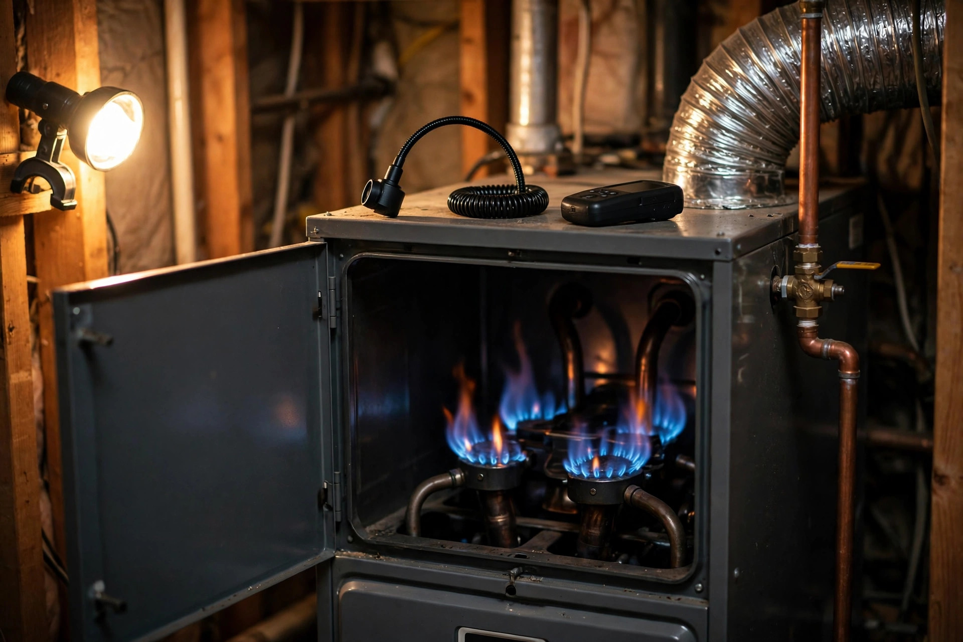
Abstract
A cracked furnace heat exchanger is one of the few appliance failures that can kill a household without any visible symptom. The exchanger is a metal wall between the combustion chamber and the air a furnace circulates through a house. When it cracks, combustion gas, including carbon monoxide, can cross into the supply air. The furnace keeps heating. The house stays warm. Carbon monoxide has no color and no odor, and the wall-mounted alarms sold for this hazard are not required to sound below 70 parts per million, so a slow leak can run for an entire heating season without tripping anything.
This disclosure turns the established manual inspection for this failure into a continuous, automated monitor. The heating industry already has a written procedure for finding these cracks, the five-step method in AHRI Guideline X, the induced-draft furnace heat exchanger inspection guideline (AHRI Guideline X-2009, superseded by AHRI Guideline X-2023, approved June 2023, which retains the same five steps): watch the flame for disturbance when the circulating blower starts, measure carbon monoxide in the return air and in the supply air and compare them, run a combustion analysis, isolate the exchanger and test it under pressure, and inspect it visually. Every step of that method is a measurement a low-cost sensor can now take on every heating cycle. This disclosure fuses four channels: a blower-coupled flame disturbance channel that samples the flame rectification current at 10 Hz or faster and time-locks it to blower start; a differential carbon monoxide channel with paired electrochemical sensors in the return and supply airstreams; a combustion acoustic channel that listens for the spectral shift a crack produces when blower air jets through it; and a scheduled automated isolation pressure test that reproduces the manual manometer test with the gas valve closed. The four channels feed a weighted crack score with per-furnace-type weights, because the physics differs between natural-draft and induced-draft furnaces, and the score drives four alert tiers: Clear, Watch, Service, and Shut down, with a positive pressure test forcing Shut down regardless of score.
- 400+ deaths per year in the US from unintentional, non-fire-related carbon monoxide poisoning
- 20,000+ emergency department visits per year for the same cause
- 230+ deaths per year attributed to carbon monoxide from fuel-burning home heating equipment (CPSC)
- 70 ppm is the lowest concentration at which a UL 2034-listed CO alarm is required to sound, and only after 1 to 4 hours
- 15 to 20 years is the typical service life of a gas furnace, and heat exchanger cracking is a late-life failure mode
For a homeowner reading this: book a furnace inspection every fall, keep a working CO alarm on every floor, and treat any furnace past 15 years as a candidate for continuous monitoring.
Field of the Invention
This invention relates to residential heating safety and predictive maintenance: continuous, automated detection of cracks in gas furnace heat exchangers using sensor fusion of flame rectification current, differential carbon monoxide concentration, combustion acoustics, and automated pressure testing.
Background
A gas furnace heats a house through a wall it never lets the house see. Burners fire inside a steel heat exchanger. Combustion gas travels through the exchanger and out the flue. House air blows across the outside of the exchanger, picks up heat, and circulates through the ducts. The wall between the two air streams is the only thing standing between a family and the exhaust of an open flame.
That wall fails by fatigue. A furnace cycles thousands of times per heating season. The exchanger expands when the burners fire and contracts when they stop. Condensate corrodes the steel, faster in high-efficiency condensing furnaces. Overfiring and restricted airflow overheat the metal. After 15 to 20 years, cracks open at welds, bends, and crimped seams. A crack does not stop the furnace. It does not trip a breaker. It does not change the thermostat reading. It lets a small fraction of combustion gas into the circulated air, every cycle, for months.
Against this failure, the standard defense is a wall-mounted carbon monoxide alarm, and it is a weak one. Under UL 2034, a listed alarm is not required to sound below 70 parts per million, and at 70 ppm it may take up to 4 hours. A cracked exchanger leaking 10 to 30 ppm into the supply air will never trip that alarm, and at those concentrations a household can still suffer headaches, dizziness, and confusion all winter without ever connecting the symptoms to the furnace. The alarm is a last-resort device for a fast, large leak. A cracked exchanger is usually a slow, small one.
Professionals defend against it with an annual inspection, and the inspection procedure is well documented. AHRI Guideline X prescribes a five-step method for induced-draft furnaces (AHRI Guideline X-2009, superseded by AHRI Guideline X-2023, approved June 2023, which retains the same five steps): first, start the furnace and watch the flame for disturbance as the circulating blower starts, because a crack lets blower air into the combustion chamber and the flame floats, rolls out, or distorts; second, measure CO in the return airstream and in the supply airstream with a 1 ppm resolution analyzer, where CO in the supply air above CO in the return air indicates a possible leak; third, verify firing rate and combustion; fourth, isolate the exchanger and apply a pressure test; fifth, disassemble and visually inspect. Field technicians add their own variants: an exchanger isolation pressure test with a manometer probe, sealing the exchanger inlet and outlet with the gas off and watching for a pressure change when the blower runs, and ambient CO measurement in the conditioned space, where anything above zero while the heat runs is worth investigating.
Each of those steps is a point-in-time measurement made once a year, by a person, with the furnace opened up. Between visits, the furnace runs thousands of cycles unobserved, and a crack that opens in December is not found until the next fall tune-up, if it is found at all. Visual inspection itself is unreliable: most of the exchanger surface is hidden behind panels and baffles, and a hairline crack that only opens when the metal is hot can look intact to a borescope on a cold furnace.
Adjacent disclosures cover parts of this ground and none of it covers the combination. LITF-PA-2026-169 trends flame rectification current over time for furnace maintenance, but it does not time-lock the signal to blower start, which is the step that separates a crack from a dirty sensor. LITF-PA-2026-189 detects incomplete combustion from flame color and flicker on consumer cameras, but it does not measure what crosses into the supply air. LITF-PA-2026-145 detects flue obstruction from acoustic resonance, but a blocked flue and a cracked exchanger are different failures with different signatures. No system known to the inventors automates the five-step method into a continuous monitor, fuses its channels into a single score, or weights the channels by furnace draft type.
What is missing is a system that runs the crack test the way the furnace itself runs: on every heating cycle, without opening the cabinet, without a technician in the house, and with a score that says how sure it is and what to do about it.
Detailed Description
1. System Architecture
A small module wired to the furnace control board does the monitoring, plus two air sensors in the ductwork. Inside the module: a microcontroller with a high-resolution analog front end, a MEMS microphone, a differential pressure sensor, and a radio. Three signals already exist on the furnace for the module to tap: the 24 V call-for-heat and blower signals from the control board, the flame sensor lead, and the gas valve state. It adds two electrochemical carbon monoxide sensors, one in the return plenum and one in the supply plenum downstream of the exchanger, and one MEMS microphone mounted on the burner compartment door. A manometer tap into the exchanger, installed by the technician at setup, gives the pressure test channel a port. Power comes from the furnace 24 V transformer, and reports go over Wi-Fi or a wired thermostat bus to a phone app and, with the homeowner's opt-in, to a technician dashboard.
All four channels are sampled on every heating cycle, and the module stores a per-cycle record: the blower-coupled flame disturbance index, the return and supply CO readings, the acoustic spectrum, and the blower and burner timing. Records are kept on the module for 90 days and summarized to a cloud service as daily aggregates. Nothing in the design requires opening the furnace cabinet after installation, and the module only ever commands the gas valve closed, never open, and only through the existing furnace safety circuit: on a Shut down decision it opens the same limit circuit a rollout switch would open, so the furnace locks out exactly as it would on any other safety fault.
2. Blower-Coupled Flame Disturbance Channel
Of all the steps in the manual test, the oldest is also the most sensitive, and it is the one this channel automates. A healthy furnace shows no change in its flame when the circulating blower starts, because the burner and the heat exchanger are sealed from the airstream. A crack breaks that seal. When the blower starts, circulating air pushes through the crack into the combustion chamber, and the flame floats, distorts, or rolls out for a few seconds until pressures equalize.
Flame rectification makes that disturbance measurable without a camera. The flame sensor is a rod sitting in the flame. The control board applies an AC voltage to it, and the flame, being a weak plasma, conducts current in one direction better than the other, rectifying the AC into a small DC current, typically 1 to 6 microamps, with a healthy sensor returning 3 to 6 microamps. Most furnace controls treat anything below about 0.5 to 1 microamp as no flame and shut the gas off. Sampling runs at 10 Hz or faster, continuously, recorded against blower timing.
Absolute current is not the diagnostic. A dirty flame sensor also lowers the current, slowly, over weeks, and that is the failure the trending disclosure in LITF-PA-2026-169 already covers. The diagnostic here is the blower-locked transient: the change in rectification current in the 10 seconds after the blower starts, compared with the 10 seconds before it. A dirty sensor drifts the baseline but produces no step at blower start. A crack produces a step at blower start on every cycle, and the step grows as the crack grows. A blower-coupled flame disturbance index, BFDI, is computed from that trace, defined as the largest relative deviation of the rectification current in the post-blower window from its pre-blower baseline, and trended across cycles and across the season. A step change in BFDI that persists across at least five consecutive heating cycles is treated as evidence, not a single-cycle spike, which a gust through a vent or a burner ignition transient can also produce.
Where the control board does not expose a flame sensor tap, the same channel falls back to a camera or a photodiode watching the flame through the inspection window, measuring flicker amplitude in the same blower-locked windows. The signal is noisier and the thresholds are wider, and the disclosure states that openly: the rectification tap is the preferred embodiment, the optical fallback is a degraded mode.
3. Differential Carbon Monoxide Channel
Differential CO is the second channel, and it automates the second step of the manual test: measure CO in the return air, measure CO in the supply air, and compare. One sensor alone cannot do this job. A house with a gas stove, a garage, or a neighbor's exhaust can carry several parts per million of CO in its indoor air, and a single supply-air sensor would alarm on the neighborhood. The diagnostic is the difference: supply minus return. Return air is the air the house already has. Supply air is that same air after passing the furnace. If the supply reading exceeds the return reading by more than the sensors' noise floor, the furnace added CO, and the only path for that is through the exchanger or the flue connection.
Two electrochemical CO sensors, one in each plenum, sample once per second during heating. During heating, a 60-second rolling mean of each sensor updates once per second, along with the difference between them. Thresholds follow the manual test: a persistent differential above 1 ppm, the resolution of the analyzer the AHRI procedure requires, is logged as a Watch-level channel signal; a persistent differential above 9 ppm, the OSHA acceptable maximum that AHRI §4.2 references for the measured airstream value, drives the CO term to its maximum and is a Service-level channel signal. Channel signals are not tier assignments: the fusion score in section 6 sets the tier, so a CO signal on its own never shuts a furnace down. Sensors are cross-calibrated weekly by the module itself: with the furnace idle and the blower running on fan-only, both sensors see the same house air, and any offset between them is recorded and subtracted. Electrochemical sensors drift and cross-react with hydrogen from charging batteries, so the module also tracks each sensor's baseline against outdoor air during shoulder-season ventilation and flags a sensor for replacement when its zero drifts beyond 2 ppm.
One limitation of this channel is explicit, and the fusion weights account for it. In an induced-draft furnace, the heat exchanger runs at negative pressure relative to the circulating air, so air leaks into the exchanger rather than flue gas leaking out. A cracked induced-draft exchanger may show no supply-air CO at all, and a CO-only monitor would clear it. The flame disturbance and pressure channels exist for exactly that case, and the per-type weighting in section 6 turns the CO weight down and the flame and pressure weights up for induced-draft units. In a natural-draft furnace the exchanger can run at positive pressure, flue gas can cross into the supply air, and the CO channel is the primary detector.
4. Combustion Acoustic Channel
Listen to the burner and a crack gives itself away in two ways. A crack changes the acoustics of the combustion chamber. First, it changes the resonant volume, shifting the spectral peaks of the burner roar in the 200 to 2000 Hz band. Second, when the blower starts, air jetting through a narrow crack adds broadband noise that a healthy chamber does not produce. The MEMS microphone on the burner compartment door samples at 16 kHz, computes a 512-point FFT every 100 ms, and records the spectrum in the same blower-locked windows the flame channel uses: 10 seconds before blower start, 10 seconds after.
S, the blower-locked spectral shift, is the change in band energy in the 200 to 2000 Hz range between the post-blower and pre-blower windows, expressed in decibels relative to the furnace's own learned baseline. A shift below 2 dB is noise. A shift above 10 dB is a strong signal. The acoustic channel is the weakest of the four on its own, because a failing blower bearing, a loose panel, or a new filter can all change the sound of a furnace, but it is cheap, it needs no ductwork, and it corroborates the flame channel: a crack produces a flame step and an acoustic step on the same cycle, while a bearing produces acoustic noise with no flame step. The fusion score treats agreement between channels as evidence and disagreement as a reason to wait for more cycles.
5. Automated Isolation Pressure Test
When the first three steps raise suspicion, a technician isolates the exchanger and pressurizes it. This channel automates that test. In the manual version, the technician places a manometer probe in the exchanger, seals the inlet and outlet as well as possible with the gas shut off, turns on the blower, and watches for a change in the exchanger. Any change indicates a leak.
Once a week, in a window when the thermostat is not calling for heat, the module runs the automated version. For the test, the gas valve closes through the furnace control circuit, the burners cool, the blower starts, and the differential pressure sensor on the manometer tap reads for 60 seconds. On a sound exchanger the reading holds steady at its learned baseline. On a cracked exchanger the blower pressure transmits through the crack and the reading shifts. A shift beyond the learned tolerance, confirmed on a repeat run the following night, is treated as confirmation of a breach, and it forces the Shut down tier regardless of the fusion score. The test runs only when the house is unoccupied or during a scheduled overnight window, and it never runs while the burners are lit. A failed test, meaning the module could not hold the gas valve closed or the pressure reading was unstable, is logged as a test failure, not as a crack, and the module retries the next night.
6. Fusion Scoring and Alert Tiers
Each heating cycle produces three normalized terms, each from 0 to 1. The flame term F is the blower-coupled flame disturbance index scaled between a 5 percent dip, which scores 0, and a 30 percent dip, which scores 1: F = clamp((BFDI - 0.05) / 0.25, 0, 1). The carbon monoxide term C is the supply-minus-return differential scaled between 1 ppm, which scores 0, and 9 ppm, which scores 1: C = clamp((ΔCO - 1) / 8, 0, 1). The acoustic term A is the blower-locked spectral shift scaled between 2 dB, which scores 0, and 10 dB, which scores 1: A = clamp((S - 2) / 8, 0, 1).
For a natural-draft furnace the crack score is R = 0.40 × F + 0.35 × C + 0.25 × A. For an induced-draft furnace, where the negative exchanger pressure makes the CO channel unreliable, the weights shift to R = 0.55 × F + 0.15 × C + 0.30 × A. The weights are provisional until measured, and the formula is stated so the table below can be checked by hand. Using ΔCO = 9 ppm as the top of the C-term scale is this disclosure's own engineering choice, not an AHRI threshold: AHRI references 9 ppm as the OSHA acceptable maximum for the measured airstream value, and this disclosure adopts it as the top of the differential scale. R is rounded to two decimals in the table.
| Case | BFDI | ΔCO (ppm) | S (dB) | R | Tier |
|---|---|---|---|---|---|
| Healthy furnace, clean sensor | 3% | 0 | 1 | 0.00 | Clear |
| Dirty flame sensor, no crack | 8% | 0 | 1.5 | 0.05 | Clear |
| Small crack, natural draft | 18% | 4 | 4 | 0.40 | Watch |
| Large crack, induced draft (reweighted) | 35% | 0 | 9 | 0.81 | Shut down |
| Crack with CO leak, natural draft | 32% | 7 | 8 | 0.85 | Shut down |
Tiers run: Clear below 0.25, Watch from 0.25 to below 0.50, Service from 0.50 to below 0.75, and Shut down at 0.75 and above. A positive isolation pressure test forces Shut down regardless of score. A tier change requires the score to hold for five consecutive heating cycles, so a single bad cycle from a gust or a power flicker never pages a homeowner. Watch sends a phone notification with the trend chart and a recommendation to book an inspection within 30 days. Service sends a notification plus a message to the homeowner's chosen technician, with the per-channel readings attached. Shut down opens the furnace limit circuit, locks the furnace out, and notifies the homeowner and the technician immediately. The lockout is never cleared automatically: it requires a technician to inspect the exchanger, replace it if cracked, and reset the module in person.
Look at the induced-draft row first. It is the case that kills people: a large crack, no CO in the supply air at all, because the exchanger runs at negative pressure. A CO-only monitor clears it. The flame term carries that row, and the reweighting is what lets it reach Shut down. The dirty-sensor row is the case that causes false alarms: a weak flame signal with no blower locking and no CO and no acoustic shift scores 0.05 and stays Clear, with a maintenance note to clean the sensor.
7. Baseline Learning and False-Positive Suppression
Every furnace has its own flame, its own sound, and its own ductwork, so every threshold in this disclosure is learned, not fixed. Its first 30 days are a learning mode, recording baselines for the rectification current, the blower-locked flame step, the return and supply CO levels, and the acoustic spectrum, across the range of outdoor temperatures and firing rates the furnace sees. Fixed thresholds in the formula above are starting points; the module replaces them with per-furnace values once learning completes, and it re-learns after any service event the technician logs, such as a flame sensor cleaning or a filter change.
Four confounders are handled explicitly. A dirty flame sensor lowers the rectification current over weeks but produces no blower-locked step, so it is separated by the time-locking. A failing blower bearing changes the acoustic spectrum but produces no flame step and no CO differential, so it scores low and is reported as a blower maintenance note. A gas stove or a garage source raises indoor CO, but it raises the return and supply sensors together, so the differential stays near zero. A cracked flue or a blocked vent changes combustion, but it changes the flame continuously rather than at blower start, and the flue obstruction disclosure in LITF-PA-2026-145 covers that failure on its own channel. Where two channels agree on the same cycle, the score trusts them; where they disagree, the score waits for five cycles before moving a tier.
8. Outputs and Consumers
- Homeowner alerts: Tier changes arrive as phone notifications with the score, the per-channel readings, and a plain-language explanation of what changed. Watch means book an inspection within 30 days. Service means book one this week. Shut down means the furnace is off, the house will cool, and a technician is already being contacted.
- Technician dashboard: With the homeowner's opt-in, the chosen technician sees the trend charts, the per-cycle records, and the pressure test history before arriving, so the visit starts with the exchanger instead of an hour of diagnostics.
- Insurance and warranty: A dated, continuous record of exchanger integrity is evidence for a warranty claim on a failed exchanger and for an insurer assessing a CO incident. The record is the homeowner's data, exportable on request, and it is not shared with an insurer without explicit consent.
- Open research data: Anonymized, aggregated crack scores by furnace model, age, and region would give the first real dataset on how often exchangers actually crack and at what age. Today that number is a guess. The disclosure proposes the dataset but does not require it: the monitor works with no cloud connection at all.
9. Figures Description
- Figure 1: System block diagram: furnace control board, flame sensor tap, blower and gas valve signals, return and supply CO sensors, burner compartment microphone, manometer tap, and the monitor module reporting to a phone app and a technician dashboard.
- Figure 2: Flame rectification current traces for a healthy furnace and a cracked furnace across blower start, showing a flat trace on the healthy unit and a step disturbance on the cracked unit, with the 10-second pre-blower and post-blower windows marked.
- Figure 3: Return and supply CO traces across a heating cycle, showing the two traces tracking together on a healthy furnace and the supply trace rising above the return trace on a cracked natural-draft furnace.
- Figure 4: Combustion acoustic spectra before and after blower start, showing the spectral shift in the 200 to 2000 Hz band on a cracked exchanger.
- Figure 5: Crack score trend over a heating season for three furnaces: a healthy unit holding near zero, a dirty-sensor unit drifting low, and a cracking unit rising from Watch to Shut down across six weeks.
Implementation Notes
Three deployment paths cover the installed base without replacing furnaces. The preferred path is a retrofit module installed by a technician during a routine tune-up: two CO sensors in the plenums, a microphone on the burner door, a tap on the flame sensor lead, and a manometer tap on the exchanger. The second path is OEM integration, where the furnace manufacturer builds the same four channels into the control board and ships the score as a diagnostic code. The third path is a smart thermostat hub, where the thermostat already knows the call-for-heat and blower timing and hosts the module, with the CO sensors as wireless plenum pucks. None of these paths requires a new furnace, a new flue, or a change to the gas line.
Calibration is per furnace, not per model. The 30-day learning window builds the baselines, and the module re-learns after any logged service event. A new installation with no history starts from the fixed thresholds in section 6 and tightens them as its own data accumulates. Furnaces with a spare flame sensor input or a second burner stage can use the second stage as a control, since a crack affects both stages and a sensor fault affects one, but the second stage is not required.
A camera-only fallback exists for furnaces whose control board does not expose a flame sensor tap. A small camera or photodiode watches the flame through the inspection window and measures flicker amplitude in the same blower-locked windows. It is disclosed as a degraded mode: the thresholds are wider, the false-positive rate is higher, and the score requires agreement from the CO or acoustic channel before leaving Clear. It is not a substitute for the rectification tap.
Costs are the cost of sensors and a microcontroller, not of a new furnace. Bill of materials for the retrofit module is under $60: two electrochemical CO sensors at roughly $12 each, a MEMS microphone at about $1.50, a microcontroller with a high-resolution ADC at about $4, a differential pressure sensor at about $6, and wiring, enclosure, and power at about $15. Installed cost is an estimated $150 to $250 as part of a tune-up visit. A heat exchanger replacement runs $1,500 to $3,500, and a furnace replacement runs $5,000 to $10,000, so the monitor pays for itself if it catches one crack one season early. That payback assumes a crack occurs within the monitor's life. The true crack rate by furnace age is unknown today, which is exactly what the open research dataset proposed in section 8 exists to measure. The expensive part is not the hardware. It is the first winter of data, which is a measurement exercise, not a capital program.
Safety posture is stated plainly. This monitor is a tripwire, not a diagnosis, and not a substitute for a professional inspection. A Shut down lockout is never cleared remotely. It never overrides a furnace safety control, never holds the gas valve open, and never restarts a locked-out furnace. Any fault in the module itself, a dead CO sensor, a disconnected microphone, a failed pressure test, fails open: the furnace runs as it did before the module was installed, and the module reports itself as offline.
A tripwire that runs on every cycle, that says how sure it is, and that waits five cycles before it speaks, is worth more than a perfect test that runs once and a silent furnace for the other 364 days.
Claims
- A system for detecting cracks in a gas furnace heat exchanger, comprising: a flame disturbance module configured to sample flame rectification current at 10 Hz or faster and to compute a blower-coupled flame disturbance index from the change in rectification current in a window after circulating blower start compared with a window before blower start; a differential carbon monoxide module comprising a first carbon monoxide sensor in a return airstream and a second carbon monoxide sensor in a supply airstream, configured to compute a supply-minus-return carbon monoxide differential; and a fusion module configured to combine the flame disturbance index and the carbon monoxide differential into a crack score and to drive an alert tier from the score.
- The system of claim 1, wherein the flame disturbance module distinguishes a crack from flame sensor fouling by time-locking the rectification current measurement to blower start, wherein fouling drifts the baseline without producing a step at blower start and a crack produces a step at blower start on consecutive heating cycles.
- The system of claim 1, further comprising a combustion acoustic module comprising a microphone mounted on a burner compartment, configured to compute a blower-locked spectral shift in the 200 to 2000 Hz band between pre-blower and post-blower windows, and wherein the fusion module combines the spectral shift into the crack score.
- The system of claim 1, further comprising an automated isolation pressure test module configured to close a gas valve, start the circulating blower, and read a differential pressure sensor on a manometer tap into the heat exchanger, wherein a pressure shift beyond a learned tolerance indicates a breach.
- The system of claim 4, wherein a positive isolation pressure test forces a shut down tier regardless of the crack score.
- The system of claim 1, wherein the fusion module applies per-furnace-type weights, with a higher weight on the flame disturbance index and a lower weight on the carbon monoxide differential for induced-draft furnaces, and a higher weight on the carbon monoxide differential for natural-draft furnaces.
- The system of claim 1, wherein the crack score is computed as a weighted sum of a flame term, a carbon monoxide term, and an acoustic term, each normalized from 0 to 1 between a noise floor and an action level, and wherein the alert tier changes only when the score holds for five consecutive heating cycles.
- The system of claim 1, further comprising a baseline learning module configured to learn per-furnace baselines for rectification current, blower-locked flame step, carbon monoxide levels, and acoustic spectrum over a 30-day learning period, and to replace fixed thresholds with the learned baselines.
- The system of claim 1, wherein the differential carbon monoxide module cross-calibrates the first and second carbon monoxide sensors by comparing their readings with the furnace idle and the blower running on fan-only, and subtracts the measured offset.
- The system of claim 1, further comprising a lockout module configured to open a furnace limit circuit on a shut down tier, wherein the lockout requires in-person technician reset and cannot be cleared remotely or automatically.
- The system of claim 1, wherein a fault in any module causes the system to fail open, wherein the furnace operates as it did before installation and the system reports itself as offline.
- The system of claim 1, further comprising a camera or photodiode fallback for the flame disturbance module, configured to measure flame flicker amplitude through an inspection window in the same blower-locked windows, and wherein the fallback requires agreement from the carbon monoxide or acoustic module before the crack score leaves a clear tier.
- The system of claim 1, further comprising a technician dashboard configured to receive per-cycle records, trend charts, and pressure test history with homeowner opt-in, and a homeowner notification module configured to send tier changes with per-channel readings and a plain-language explanation.
- A method for detecting cracks in a gas furnace heat exchanger, comprising: sampling flame rectification current at 10 Hz or faster across circulating blower start on every heating cycle; computing a blower-coupled flame disturbance index from the change in rectification current after blower start compared with before blower start; measuring carbon monoxide in a return airstream and in a supply airstream and computing a supply-minus-return differential; combining the flame disturbance index and the carbon monoxide differential into a crack score with per-furnace-type weights; and driving an alert tier from the crack score, including opening a furnace limit circuit on a shut down tier.
Prior Art References
- CDC, Carbon Monoxide Poisoning 2019 Case Definition: approximately 450 deaths and 21,000 emergency department visits per year from unintentional, non-fire-related CO poisoning
- AHRI Guideline X-2023, Induced Draft Furnace Heat Exchanger Inspection: supersedes AHRI Guideline X-2009 and retains the five-step method: flame disturbance at blower start, differential CO in return and supply airstreams, combustion verification, isolation pressure test, visual inspection
- HVAC School, Heat Exchanger Crack Diagnosis: flame displacement at blower start, ambient CO measurement, combustion analysis, exchanger isolation pressure test with manometer, negative pressure behavior of induced-draft exchangers
- LITF-PA-2026-169: Predictive furnace maintenance via flame rectification current trending
- LITF-PA-2026-189: Residential gas burner incomplete-combustion detection via flame chromaticity and flicker analysis on consumer cameras
- LITF-PA-2026-145: Automated residential flue obstruction detection via acoustic resonance spectroscopy and differential pressure sensing
- UL 2034, Standard for Single and Multiple Station Carbon Monoxide Alarms: alarms not required to sound below 70 ppm; required to sound at 70 ppm within 60 to 240 minutes
- U.S. Energy Information Administration, Residential Energy Consumption Survey: roughly half of US households heat primarily with natural gas
- U.S. Department of Energy, Furnaces and Boilers: typical gas furnace service life of 15 to 20 years
- OSHA, 29 CFR 1910.1000 Table Z-1: carbon monoxide permissible exposure limit of 50 ppm as an 8-hour time-weighted average
- NFPA 72, National Fire Alarm and Signaling Code: carbon monoxide detection and alarm placement requirements
- ASHRAE Standard 62.2, Ventilation and Acceptable Indoor Air Quality in Residential Buildings: ventilation rates governing indoor CO dilution
- 35 U.S.C. § 102(a)(1): Prior art; printed publications available to the public before the filing date
- CPSC, Inspecting Your Home Heating System Before Winter Could Save Your Life: more than 230 deaths attributed each year to carbon monoxide poisoning associated with fuel-burning home heating equipment
Limitations
Nothing in this disclosure has been validated against measurements from real furnaces. The fusion weights, the 5 percent and 30 percent BFDI bounds, the 1 ppm and 9 ppm CO bounds, the 2 dB and 10 dB acoustic bounds, and the five-cycle tier hold are engineering estimates stated so they can be tested. No cracked exchanger has been measured with this system, and the table in section 6 is a worked example, not a result.
Three failure modes bound what this system can do. First, the physics cuts against the CO channel on the most common modern furnace: an induced-draft exchanger runs at negative pressure, so air leaks in and flue gas does not leak out, and a CO-only reading will clear a cracked induced-draft unit. The reweighting in section 6 is the answer, but it is an answer that depends on the installer entering the furnace type correctly, and a misconfigured unit will weight the wrong channel. Second, electrochemical CO sensors drift, and they cross-react with hydrogen, so a home with a battery bank charging in the same airspace can produce a differential that looks like a leak. The weekly fan-only cross-calibration catches slow drift but not a fast cross-reaction. Third, the flame channel depends on a tap the installer can reach and a control board that tolerates one. Some boards do not expose the flame sensor lead, and on those furnaces the camera fallback is weaker and noisier, which means the strongest channel is the one most likely to be unavailable on the cheapest furnaces, which are also the oldest and the most likely to crack.
A Shut down lockout in cold weather leaves a household without heat, which carries its own risk: frozen pipes and, for vulnerable occupants, hypothermia. That cost is why the five-cycle hold and the pressure-test confirmation exist: a lockout should be hard to trigger by accident.
A person with a borescope remains the gold standard, and that is the strongest case against this approach. This system is a tripwire, not a diagnosis. A professional inspection sees the crack. This system sees its shadow: a flame that flinches, a few parts per million in the supply air, a shift in the sound of the burner. Shadows can be cast by other things, and a system that cries crack on a dirty sensor or a failing bearing will teach homeowners to ignore it, which is worse than having no monitor at all. The case for this disclosure is not that the tripwire replaces the inspection, but that the inspection happens once a year and the crack can open the week after it. A tripwire that runs on every cycle, that says how sure it is, and that waits five cycles before it speaks, is worth more than a perfect test that runs once and a silent furnace for the other 364 days. Where the system is unsure, it must say Watch, not Shut down, and where it has no data at all, it must say nothing and report itself offline.