System and Method for Predictive Maintenance of Gas-Fired Furnaces Using Flame Rectification Current Trending and Ignition Failure Signature Analysis
Abstract
Disclosed is a system and method for predicting ignition failure in residential gas furnaces before it strands a homeowner without heat. Every gas furnace proves flame through flame rectification: the control board drives roughly 100 VAC onto a metal flame sensor rod, and the ionized flame plasma conducts a small DC current, typically 1 to 6 microamps, back through the burner ground. When that current falls below the board's flame-prove threshold (commonly near 1 microamp), the board shuts the gas valve and, after three to five failed trials, locks out entirely. The disclosed system continuously samples the flame rectification current across heating cycles, computes per-cycle steady-state values, and trends them over weeks and months. A declining trend is extrapolated against the flame-prove threshold to estimate days until failure, and the shape of the decline is classified into failure signatures: gradual monotonic decay indicating carbon and oxidation buildup on the rod, abrupt step drops indicating cracked insulators or thermal shock, and noisy intermittent readings indicating a degrading burner ground path. The system fuses this trend with ignition-attempt counts and lockout history, issues a maintenance alert well before the first failed call for heat, and, in a retrofit embodiment, installs as an inline harness adapter that requires no modification to the furnace control board. The invention converts the most common residential no-heat service call into a scheduled 15-minute cleaning.
Field of the Invention
This invention relates to residential HVAC maintenance, specifically to continuous monitoring of flame rectification current in gas-fired forced-air furnaces, trending that signal to predict flame sensor and burner-ground degradation, and alerting homeowners or service contractors before ignition lockout occurs.
Background
More than half of U.S. households use natural gas for space heating, with 61% using natural gas for at least one energy end use (EIA, 2020 Residential Energy Consumption Survey). The dominant heat source in those homes is the gas-fired forced-air furnace, and its single most common failure is the flame sensor. A dirty or oxidized flame sensor is consistently ranked by field technicians as the leading cause of furnaces that ignite and then shut down after a few seconds (Remove and Replace, 2026).
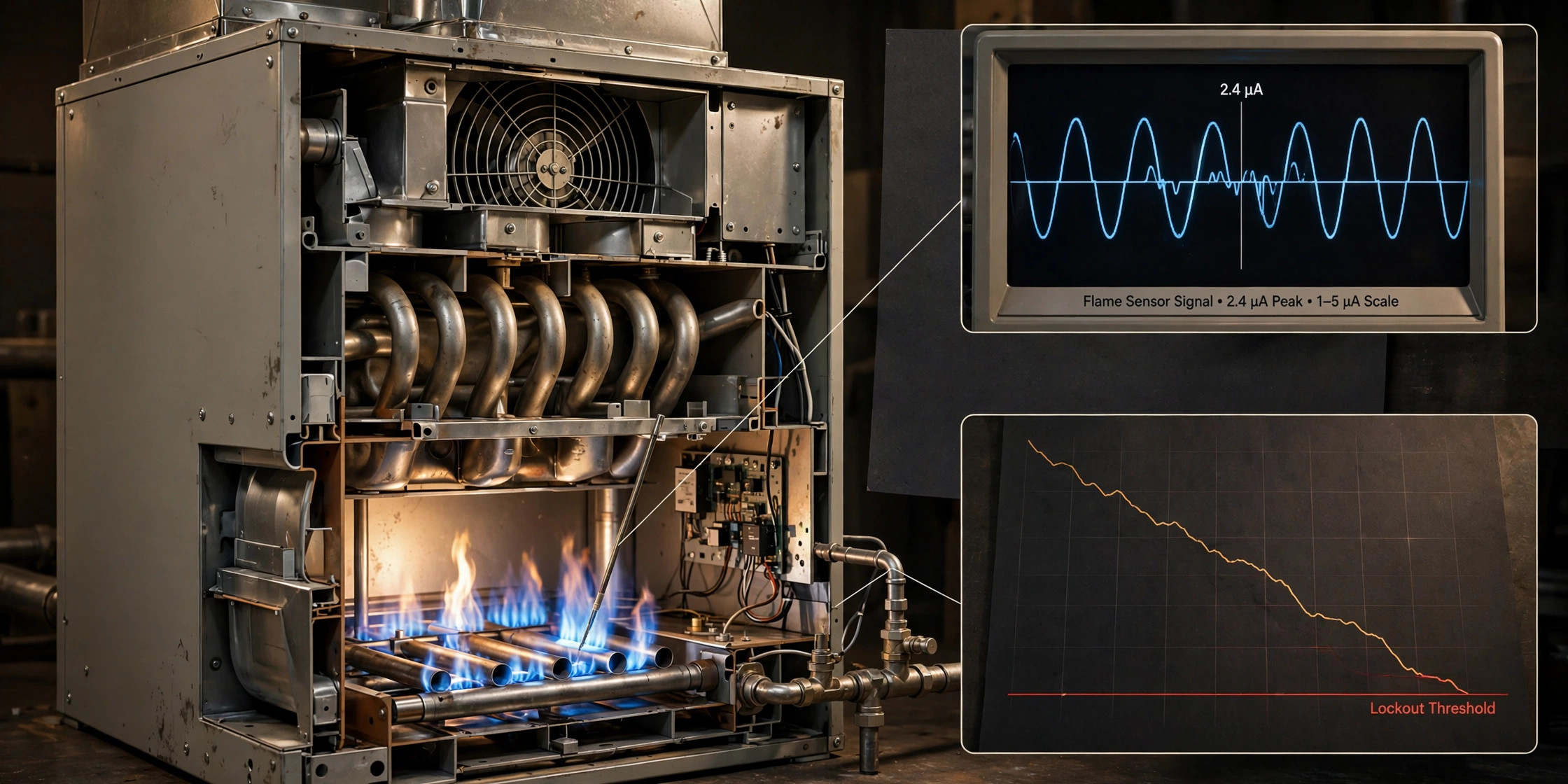
Flame rectification is the mechanism every modern furnace uses to prove flame. The control board applies roughly 100 VAC from a high-impedance source to the sensor rod. The flame's ionized gases conduct current preferentially in one direction because of the large surface-area asymmetry between the thin rod and the much larger burner ground plane, so the AC is rectified into a small pulsating DC that the board measures. A healthy sensor returns 3 to 6 microamps DC; 1 to 2 microamps is borderline; below roughly 1 microamp the board declares no flame and closes the gas valve (Carl's Cooling, furnace flame sensor guide).
The degradation physics are slow and measurable. Combustion deposits carbon and oxide films on the sensor rod over one to two heating seasons, insulating the microamp signal in exactly the way corrosion on a battery terminal kills a connection while the wire itself remains intact. Loose or corroded burner ground connections produce a second failure mode with an intermittent, noisy signature. Neither failure is sudden. The signal degrades over months while the furnace runs normally, until one cold morning the current crosses the threshold, the board exhausts its ignition trials, and the furnace locks out. The homeowner discovers this at 6 AM in January. The service call costs $150 to $250 for what is, in the end, a cleaning task that takes 10 to 20 minutes with emery cloth or a replacement sensor costing $10 to $20.
The annual fall tune-up does not close this gap. A technician cleans the rod in October, the flame current resets to its baseline, and the contamination resumes with the first firing; by February the signal can be below threshold again with no record that it was trending there. Preventive maintenance resets the clock but never watches it.
Current technology measures flame current only as a binary safety signal or as a one-time diagnostic. Control boards compare the instantaneous current against the flame-prove threshold each cycle and never record history. Communicating systems such as Carrier Infinity and Lennox iComfort report fault codes after a failure has already occurred. Technicians measure flame current with handheld meters during service visits, but a single measurement cannot show a trend, and most visits happen after the failure. Industrial process burners have advanced diagnostics that trend burner parameters and alarm on flame instability (Emerson Rosemount white paper), but those systems address large process furnaces with different sensor physics and do not apply to residential flame rectification circuits. Predictive maintenance literature for residential HVAC monitors temperature, pressure, airflow, vibration, and power draw (Lessen, 2026) but does not include the flame rectification current as a trended predictive signal.
The gap in the art is a residential system that records the flame rectification current across cycles, establishes each furnace's individual baseline, detects the decline signature before the threshold is crossed, distinguishes contamination from ground-path and insulator failures, and converts the finding into a scheduled maintenance action. No reference teaches continuous trending of the residential flame sense signal for failure prediction.
Detailed Description
1. Signal Acquisition
The system measures the DC component of the flame rectification current in series with the flame sensor lead, or in parallel across the control board's sense resistor, with a resolution of at least 0.1 microamps and a range of 0 to 20 microamps DC. In the integrated embodiment, the measurement circuit is part of the furnace control board and samples the current once per second during each burner firing. In the retrofit embodiment, an inline harness adapter inserts a low-burden sense resistor between the existing sensor wire and the board terminal, digitizes the resulting voltage with an isolated analog-to-digital converter, and transmits readings via BLE or WiFi to a thermostat or gateway. The retrofit draws power from the furnace's 24 VAC transformer through an isolated supply and requires no change to the board, the sensor, or the gas train.
Each burner firing produces one per-cycle record containing: the steady-state flame current (median of samples taken 15 to 60 seconds after ignition, after warmup transients settle), the peak inrush current during ignition, the cycle's ignition-attempt count, the total burn duration, and a timestamp. Sampling only after the 15-second mark excludes cold-start transients in which the flame plasma has not stabilized.
2. Baseline Establishment and Trend Computation
Over the first 30 days of operation (or the first 200 burner cycles, whichever comes first), the system computes the furnace's baseline flame current as the median steady-state value, along with a per-cycle noise estimate from the within-cycle standard deviation. Typical baselines fall between 2 and 6 microamps depending on rod geometry, burner type, and ground quality, so a fixed global threshold would either alarm constantly on marginal-but-stable installations or miss degradation on high-baseline ones. The individual baseline is therefore the reference for all subsequent trending.
The system maintains two exponential moving averages of the steady-state current: a fast average with a time constant of approximately 7 days and a slow average with a time constant of approximately 60 days. The difference between the slow average and the baseline gives the long-term drift; the difference between the fast and slow averages detects recent acceleration of the decline. A least-squares fit over the trailing 90 days of steady-state values yields the decline slope in microamps per day. Dividing the margin between the current value and the flame-prove threshold by the slope produces the estimated days to failure, which is reported to the user once the estimate falls below 90 days.
3. Failure Signature Classification
Not all declines demand the same response, so the system classifies the observed trajectory:
- Gradual monotonic decay: slow decline of 0.005 to 0.05 microamps per day with low cycle-to-cycle noise. This is carbon and oxide contamination of the rod. Response: schedule sensor cleaning at the next convenient time, with an estimated date derived from the days-to-failure calculation.
- Abrupt step drop: a sudden decline of more than 1 microamp within a single week, with no recovery. This indicates a cracked ceramic insulator, a shifted rod position, or thermal-shock damage. Response: immediate inspection alert, because the signal is now one mechanical event away from the threshold.
- Intermittent noisy readings: cycle-to-cycle standard deviation rising above 25% of the mean while the slow average remains near baseline. This indicates a degrading burner ground path: loose burner screws, corroded ground wires, or a failing ignition ground. Response: alert directing inspection of ground connections, which cleaning the rod alone will not fix.
- Stuck or saturated reading: steady-state current pinned near the ADC rail or showing zero variation across cycles. This indicates a measurement-chain fault rather than a flame fault. Response: self-diagnostic alert for the sensing module itself.
4. Ignition Attempt Fusion
The system fuses the current trend with ignition-attempt telemetry. A furnace that begins requiring two or three ignition trials before a successful burn, while its flame current trends downward, is experiencing marginal flame proving even before any lockout: the flame exists but the weakened signal occasionally falls below threshold during a single trial. Each multi-trial cycle increments a retry counter, and the alert priority escalates when retries occur in more than 5% of cycles over a 14-day window. Lockout events, when they do occur, are logged with the current trend state so the system can correlate and refine its days-to-failure model for that furnace model across the installed base.
5. Model-Specific Threshold Learning
Where the system has cloud connectivity and the homeowner opts in, anonymized trend records (furnace make and model, baseline current, decline slope, failure signature class, and confirmed failure outcomes) are aggregated across the installed base. For each furnace model, the system learns the empirical distribution of baselines and the typical decline rate of contamination failures, which sets model-specific warning margins. A model whose boards prove flame at 0.5 microamps needs a different margin than one that trips at 1.5 microamps. This fleet learning improves the days-to-failure estimate without ever accessing a home's identity: records carry only model identifiers and signal statistics.
6. Alerting and Maintenance Scheduling
Alerts are delivered through the communicating thermostat display, a companion mobile application, or a contractor dashboard, in plain language tied to the classified signature: "Your furnace's flame sensor signal has declined 40% since October. Cleaning is recommended within the next 6 weeks, before the heating season peaks." A contractor dashboard lists monitored furnaces ranked by days to failure, allowing service companies to batch cleanings into scheduled visits during shoulder seasons instead of dispatching emergency no-heat calls at premium rates in January. With homeowner authorization, the system can request a service appointment automatically when the estimate falls below 21 days.
7. Self-Test and Measurement Integrity
Once per week, during a burner-off period, the system injects a known reference current through the sense chain and verifies the digitized value matches within 2%, confirming the measurement circuit has not drifted. A failed self-test generates a sensing-module fault alert distinct from any furnace fault. This prevents a degrading measurement circuit from either masking a real decline or generating false maintenance alerts.
8. Figures Description
- Figure 1: System block diagram showing the flame sensor rod, burner ground plane, control board with integrated sense circuit, and the alerting path to thermostat and mobile application; alternate retrofit embodiment shown with inline harness adapter and wireless link.
- Figure 2: Representative 18-month flame rectification current trace showing baseline establishment, gradual monotonic decay from carbon buildup, and crossing of the flame-prove threshold with the predicted failure date marked.
- Figure 3: The four failure signatures (gradual decay, step drop, intermittent noise, saturated reading) with their characteristic current traces and the recommended response for each.
- Figure 4: Retrofit harness adapter detail: sense resistor, isolated ADC, wireless module, and power tap from the 24 VAC transformer, inserted between the existing sensor wire and the control board terminal.
Claims
- A system for predictive maintenance of a gas-fired furnace, comprising: a current sensing circuit that measures the DC component of the flame rectification current conducted through the flame sensor rod during burner firings; a recording module that stores per-cycle steady-state flame current values over a plurality of heating cycles; and a trend analysis module that computes a decline trajectory of the steady-state values relative to an established baseline and estimates a time remaining before the flame current crosses a flame-prove threshold.
- The system of claim 1, wherein the baseline is computed as the median steady-state flame current over an initial commissioning period of at least 30 days or 200 burner cycles, and wherein the trend analysis module maintains a fast moving average with a time constant of days and a slow moving average with a time constant of months, using the difference between the averages to detect acceleration of the decline.
- The system of claim 1, further comprising a signature classification module that distinguishes: (a) gradual monotonic decay indicating sensor rod contamination, (b) abrupt step decline indicating insulator cracking or rod displacement, (c) intermittent noisy readings indicating burner ground path degradation, and (d) saturated or invariant readings indicating a sensing-module fault, and that assigns a maintenance response corresponding to each classified signature.
- The system of claim 1, further comprising an ignition-attempt fusion module that records the number of ignition trials per cycle, detects multi-trial cycles indicative of marginal flame proving, and escalates the maintenance alert when retries exceed a configurable fraction of cycles over a trailing window.
- The system of claim 1, further comprising a self-test module that injects a known reference current through the sensing circuit during burner-off periods and verifies measurement accuracy within a tolerance, generating a distinct sensing-module fault alert on failure.
- The system of claim 1, wherein the current sensing circuit is implemented as a retrofit inline harness adapter comprising a low-burden sense resistor, an isolated analog-to-digital converter, and a wireless transmitter, installed between the existing flame sensor wire and the control board terminal without modification to the furnace control board, sensor, or gas train, and powered from the furnace's low-voltage transformer.
- The system of claim 1, further comprising a fleet learning module that aggregates anonymized trend records keyed by furnace make and model to establish model-specific baseline distributions and flame-prove thresholds, improving the time-remaining estimate for individual furnaces of the same model.
- A method for preventing ignition lockout in a gas-fired furnace, comprising: sampling the flame rectification current across a plurality of burner firings; computing per-cycle steady-state flame current values after warmup transients; establishing an individual furnace baseline from an initial commissioning period; fitting a decline slope to the steady-state values over a trailing window; dividing the margin between the current value and the flame-prove threshold by the decline slope to estimate days until failure; and issuing a maintenance alert when the estimate falls below a warning threshold.
- The method of claim 8, further comprising scheduling a sensor cleaning or ground-path inspection through a contractor dashboard that ranks a plurality of monitored furnaces by estimated days until failure, enabling batched shoulder-season service visits.
- The method of claim 8, wherein the per-cycle record further comprises peak ignition current, ignition-attempt count, burn duration, and timestamp, and wherein steady-state values are computed from samples taken at least 15 seconds after ignition.
Prior Art References
- U.S. Energy Information Administration, "The majority of U.S. households used natural gas in 2020": 61% of households used natural gas for at least one end use; more than half used it for space heating (2020 RECS)
- Remove and Replace, "Furnace Keeps Igniting Then Shutting Off?" (2026): dirty flame sensor ranked most common cause; healthy range 3-6 µA, failure below ~1 µA; service call $150-250, sensor $10-20
- Carl's Cooling, "Furnace Flame Sensor: Ultimate Fix Guide" (2025): flame rectification explained; normal operating range 1-6 µA DC; board cuts gas on signal loss
- Emerson Rosemount, "Furnace Flame Instability Detection with Advanced Pressure Diagnostics" (white paper): trending of burner diagnostics and alerting in industrial process furnaces
- Lessen, "Future-Proof Your HVAC Service Business with Predictive Maintenance" (2026): IoT predictive maintenance for HVAC using temperature, pressure, airflow, vibration, and power draw telemetry
- Carrier Infinity System Control: communicating thermostat with post-failure fault code reporting
- AIChE, "Furnace Flame Instability Detection Using Pressure Measurement" (conference presentation): early detection of burner flame instability via standard deviation of pressure signal
Implementation Notes
The preferred sensing resolution of 0.1 microamps is well within the capability of commodity 16-bit ADCs with appropriate front-end amplification; the challenge is isolation and burden, not precision. The inline retrofit must present less than 10 ohms of series resistance to the sense lead so the board's high-impedance source is unaffected, and the isolated supply must not inject common-mode noise into the rectification measurement. Galvanic isolation rated to 1500 VAC between the 24 VAC power tap and the sense front end is recommended.
Threshold selection should be conservative on the alert side: a homeowner who cleans a sensor six weeks early loses nothing, while a missed prediction costs an emergency call. The 90-day warning and 21-day automatic-scheduling thresholds reflect this asymmetry. Burner-off self-test scheduling should avoid the first 60 seconds after flame-out, when residual ionization can contaminate the reference measurement.
Fleet aggregation must strip all household identifiers before upload and should transmit only model codes and signal statistics. The model-specific thresholds learned from the fleet are a tuning input, not a substitute for each furnace's individual baseline.