System and Method for Prognostic Health Monitoring of Residential Standby Generators Using Exercise-Cycle Acoustic, Vibration, and Electrical Signatures
Abstract
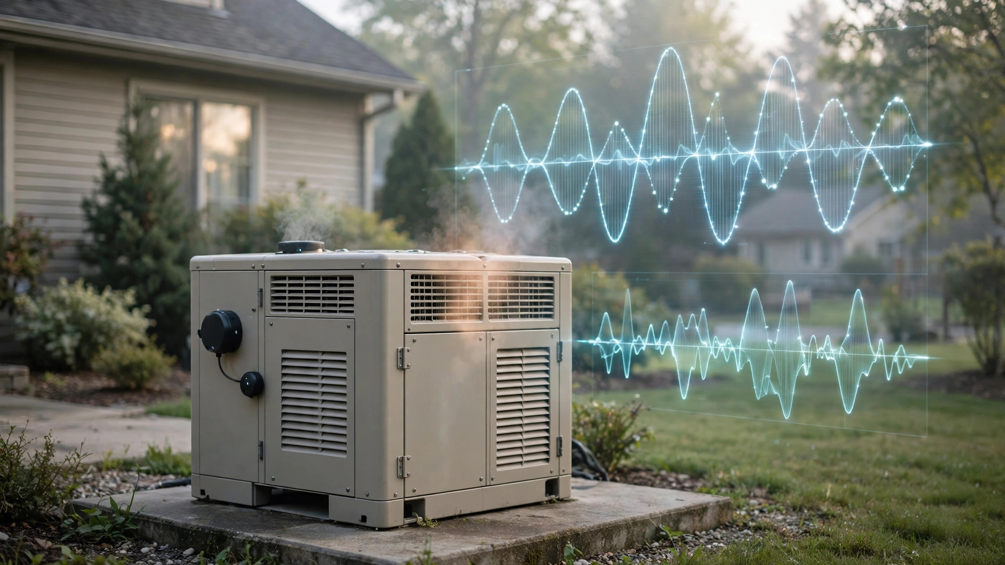
Disclosed is a system and method for prognostic health monitoring of residential automatic standby generators that treats the mandated weekly exercise cycle as a controlled diagnostic stimulus rather than a pass/fail self-check. A retrofit sensor kit combines three non-invasive measurement channels: a weatherproof MEMS microphone that records the engine acoustic signature, a tri-axial MEMS accelerometer magnet-mounted to the generator frame that records the vibration signature, and a fused voltage tap at the starting battery that records crank-phase voltage with millisecond resolution. An edge hub segments every exercise cycle into crank, run-up, steady-run, and shutdown phases, then extracts prognostic features: crank voltage valley depth and valley-to-valley recovery slope as a battery state-of-health indicator, crank duration and retry count as starter and fuel-system indicators, firing-frequency harmonic energy and per-cycle energy variation as combustion-health indicators, and run-up time plus frequency-settling behavior as governor and fuel-delivery indicators. Features are compared against an adaptive per-installation baseline learned during a commissioning window of consecutive exercise cycles, with temperature compensation for battery and acoustic behavior. A fault-decoupling module separates battery degradation, starter wear, ignition faults, fuel-delivery degradation, and governor faults by their directional signature movements. A graduated response reports a weekly readiness score, maintenance scheduling guidance at the watch tier, a will-likely-fail warning with the failing subsystem named at the alert tier, and an exercise-failure critical alert when the unit fails to start during its own self-test.
Technical Field
This disclosure relates to condition monitoring of engine-driven standby power equipment, specifically to prognostic health assessment of residential automatic standby generators through non-invasive acoustic, vibration, and electrical signature analysis of their recurring exercise cycles, fused at the edge with per-installation adaptive baselines.
Background
Residential standby generators are the most expensive insurance policy most homeowners never think about. A permanently installed unit (typically 10 to 26 kW for a single-family home) connects to the home's natural gas or propane supply and its electrical panel through an automatic transfer switch, and starts itself within seconds of a utility outage. Generac pioneered the category in 1959 and remains the market leader; independent dealer analyses put the company's share of the North American residential standby market near 45 percent, with Frost and Sullivan data cited by Generac indicating 4 out of 5 homeowners who buy a standby unit choose Generac. Kohler, Cummins, and Briggs and Stratton compete for the remainder. The installed base is large and growing: roughly 6.5 percent of US single-family homes already own a standby unit, per Generac's second-quarter 2026 earnings commentary. A typical installed cost runs $4,000 to $8,000 for equipment plus installation, with total quotes commonly reaching $10,000 to $14,000 once gas plumbing, electrical work, permits, and a concrete pad are included.
The defining reliability problem is that the machine sits idle for months and must then work perfectly on the worst day of the year. Battery failure is the leading cause of standby generators failing to start, according to Generac dealer service data: unlike a car battery that recharges during daily driving, a standby battery sits for months between cranks, slowly self-discharging, and the unit's own trickle charger masks the decay until the morning it matters. The other common failure modes are fuel-system degradation (stale fuel, clogged filters, regulator drift on propane systems), ignition faults (fouled or worn spark plugs), governor and voltage-regulator drift, transfer-switch contact failure, and rodent or insect damage to wiring. Homeowners discover these failures during outages, when service technicians are booked solid and parts are scarce.
Manufacturers address the idle problem with the exercise cycle. Generac's Quiet-Test mode runs the unit weekly for 5 or 12 minutes at reduced RPM (2,400 RPM on older 16 and 18 kW units versus the 3,600 RPM operating speed), producing 55 to 57 dB(A) at exercise versus 61 to 67 dB(A) under load. Kohler units exercise weekly for 20 minutes with a configurable schedule through the RDC2 controller. The exercise is a pass/fail self-check: the controller confirms the engine started and ran, and logs an alarm if it did not. NFPA 110, the Standard for Emergency and Standby Power Systems, goes further for covered facilities: it requires a weekly inspection and a monthly exercise of at least 30 minutes at no less than 30 percent of nameplate load (8.4.2), because unloaded short exercises do not validate full-load capability. Residential units are generally not NFPA 110 installations, but the principle transfers: a short unloaded weekly run proves the engine turns over, and proves almost nothing else.
Remote monitoring products exist, but they report controller alarms after failure rather than predicting failure before it. Generac's Mobile Link system (standard on current Guardian models) reports generator status, runtime hours, exercise timing, maintenance schedules, and fault codes to a phone app, with dealer-managed plans giving the servicing dealer the same data. Kohler's OnCue Plus system monitors the generator, the RXT automatic transfer switch, battery voltage, frequency, and a time-stamped event history, and sends exercise-start, exercise-end, warning, and shutdown notifications. These are telemetry mirrors of the controller's own pass/fail state. Neither performs prognostic analysis of the exercise waveform, and neither maintains a per-installation trend of the physical signatures that precede failure.
The patent literature covers generator status communication and control, not exercise-cycle prognostics. US20110291847A1 (Generac) discloses power-line-carrier communication of standby generator status and error codes to a remote display. US8841797B2 (Generac) discloses a wireless annunciator for an electrical generator. US9563217B2 discloses optimizing generator start delay and runtime following an outage based on load profiles. US20240380344A1 discloses a remotely controlled generator with communication receiver and transmitter. Each of these moves status information or control commands; none analyzes the acoustic, vibration, or electrical signature of the exercise cycle to predict future failure.
The academic literature validates the individual sensing techniques but never assembles them into this system. Rojas Espinoza and colleagues demonstrated injector and ignition fault diagnosis in internal combustion engines from acoustic signals alone, using Symmetrized Dot Pattern transforms and convolutional neural networks at 81.11 percent accuracy on 540 recordings (MDPI Sensors, 2026). Firmino and colleagues detected engine misfire from combined vibration and acoustic analysis (Journal of the Brazilian Society of Mechanical Sciences and Engineering, 2021). On the electrical side, Virginia Tech theses by Kerley and others established that lead-acid battery state of health can be estimated from the cranking voltage waveform alone: a healthy battery's voltage rises from the first cranking valley to the second, while a failing battery's voltage keeps falling as chemistry fails to keep up with current demand, and a low-cost microcontroller prototype implemented the algorithm at 144 mW active power. Onori and colleagues at Ohio State developed on-board capacity estimation methods for lead-acid batteries from everyday operational data. These are laboratory and automotive techniques; none has been applied to the weekly exercise cycle of a standby generator.
The strongest case against this system is that it is unnecessary: manufacturers already monitor exercise cycles, and anything worth knowing shows up as a controller alarm. That case is weaker than it looks. Controller alarms are binary and late. A Generac Evolution controller logs an overcrank alarm after the engine has already failed to start five times; it reports low battery voltage against a fixed threshold that cannot distinguish a cold morning from a dying cell; and it says nothing at all about the gradual changes, lengthening crank, softening combustion, widening governor band, that precede the alarm by weeks or months. Mobile Link faithfully relays these alarms to the homeowner's phone, which means the homeowner learns about the failure at the same moment the controller does: after it has happened. The second objection is acoustic: a microphone outside an enclosure in a suburban yard hears lawnmowers, traffic, and rain. The answer is repetition. The exercise happens at the same time every week, and the analysis compares each exercise against the unit's own history, not against an absolute sound level. Transient yard noise corrupts individual exercises, which the system detects and excludes; it cannot fake a six-week trend in crank voltage valley depth, because the voltage tap does not hear the lawnmower.
The gap in the art is a complete deployable system that: (a) treats the already-mandated weekly exercise cycle as a recurring controlled diagnostic stimulus, extracting prognostic signal from an event the homeowner's equipment already performs 52 times per year; (b) does so with fully non-invasive external sensors (microphone, frame-mounted accelerometer, battery voltage tap) requiring no modification to the engine, fuel system, alternator, or controller; (c) analyzes the crank phase specifically, because the crank is the single highest-stress electrical event the system ever performs and the phase where battery and starter failures first reveal themselves; (d) self-calibrates to each specific installation through a commissioning baseline, since engine models, enclosure acoustics, mounting pads, and ambient conditions vary; (e) decouples the five dominant failure modes by directional signature tests rather than thresholding a single channel; and (f) converts the analysis into a weekly readiness verdict the homeowner can act on before the next outage.
Detailed Description
1. The exercise cycle as a controlled diagnostic stimulus
Every residential standby generator already performs the same experiment every week. The controller initiates a start sequence at a scheduled time, the starter motor cranks the engine, the engine catches and runs up to exercise speed, it runs unloaded for the configured duration (5 or 12 minutes on Generac Quiet-Test units, 20 minutes on Kohler RDC2 units), then shuts down and returns to standby. The stimulus is highly repeatable: same start sequence, same speed target, same duration, same load (none), week after week, 52 times per year. This repeatability is what makes prognostics possible. Any drift in the response to this fixed stimulus is, by construction, drift in the machine rather than drift in the test conditions, once ambient temperature is compensated. The system therefore never needs to command a test run; it passively observes the tests the equipment already performs, which also means it works on units whose controllers cannot be modified and requires no cooperation from the manufacturer.
The hub segments each exercise into four phases by combined acoustic onset and voltage events. The crank phase runs from starter engagement (battery voltage drops sharply, acoustic onset of the starter whine) to first sustained combustion (voltage recovers toward charger level, acoustic onset of firing). The run-up phase runs from first combustion to steady exercise speed (frequency settles to the exercise target, 40 Hz firing fundamental at 2,400 RPM or 60 Hz at 3,600 RPM for a twin-cylinder four-stroke). The steady-run phase is the remainder of the exercise. The shutdown phase covers fuel shutoff through crankshaft stop. Phase boundaries are detected from the sensor data, not from controller signals, so the system works even when the controller offers no data interface.
2. Sensor kit hardware
The kit contains no sensor inside the engine, the fuel system, the alternator, or the controller. Every element mounts externally and is installable by a homeowner with basic tools:
- One weatherproof MEMS microphone (IP65, 20 Hz to 20 kHz, 120 dB SPL handling) mounted on a short standoff outside the enclosure, aimed at the engine compartment, recording 16-bit audio at 16 kHz during exercise only. A windscreen and a high-pass filter at 15 Hz suppress wind and handling noise.
- One tri-axial MEMS accelerometer (±16 g range, 1.6 kHz output data rate class, unit cost near $4) magnet-mounted to the generator's steel frame rail inside the enclosure or to the enclosure's structural channel, recording vibration at 1.6 kHz during exercise only. Mounting on the frame rather than on enclosure sheet metal avoids panel resonances that vary with how tightly each panel is fastened.
- One fused battery voltage tap connected at the starting battery terminals (typical Group 26R 12 V automotive battery) through an inline 1 A fuse, sampling battery terminal voltage at 1 kHz with millisecond timestamping during the crank phase and at 1 Hz during standby. This is the only electrical connection in the kit; it draws under 50 mA and does not modify the generator's wiring.
- One ambient temperature and humidity sensor (BME280 class) in the hub enclosure, used for battery temperature compensation and acoustic propagation correction.
- One edge hub (ESP32-S3 class microcontroller with WiFi and BLE, unit cost near $6) that buffers the exercise recording locally, runs the full analysis pipeline on-device, stores 52 weeks of per-exercise features locally, and reports results. A cloud mirror is optional; no embodiment requires continuous connectivity for the core diagnosis.
In one embodiment, a plug-in outlet module (a second ESP32-class device in a wall-wart form factor inside the home) monitors utility-side voltage at 1 Hz and timestamps any transfer-switch operation during exercise or outage, supporting the transfer-switch verification of Section 8. Target bill-of-materials cost for the full kit, including the outlet module, is under $40.
3. Crank-phase battery and starter analysis
The crank phase is the richest prognostic window in the entire exercise because it is the highest-current event the system ever performs: the starter draws several hundred amperes from a battery that has sat idle for a week. The unit's own trickle charger (2.5 A on Kohler RDC2 controllers) holds the terminal voltage at float between exercises, which masks capacity decay from the controller's fixed low-voltage threshold: the controller sees a healthy float voltage right up until the crank demand exposes the lost capacity. The hub records the battery terminal voltage waveform from 500 ms before starter engagement through starter disengagement, and extracts three features validated in the battery literature. First, valley depth: the minimum voltage reached during cranking, temperature-compensated, where a healthy 12 V battery stays above approximately 9.6 V at temperatures above freezing and dips below 9 V indicate a battery that needs attention. Second, valley-to-valley recovery slope: the voltage waveform during cranking shows successive valleys as each compression stroke loads the starter; in a healthy battery each valley is shallower than the last as the voltage-current relationship stays near-ohmic, while in a failing battery successive valleys deepen because the chemistry cannot keep up with current demand (Kerley, Virginia Tech). Third, crank duration and attempt count: the time from starter engagement to first sustained combustion, and the number of crank attempts before the engine catches, where a lengthening crank trend indicates starter wear, weakening battery, or fuel-delivery degradation, and a second or third attempt where the baseline needed one indicates a fault developing in the start chain.
Temperature compensation is essential because battery capacity falls sharply in cold weather while the engine simultaneously becomes harder to crank. The hub applies a per-installation temperature derating learned from the commissioning window: valley depth is compared against the expected value at the measured ambient temperature, not against a fixed threshold. A battery that sags to 9.2 V at minus 10 C may be healthy; the same sag at 25 C is not. The battery state-of-health estimate fuses valley depth, recovery slope, and crank duration into a single 0 to 100 score with a stated uncertainty band, and projects a replacement window in weeks based on the trend slope across recent exercises.
4. Run-phase acoustic and vibration signature analysis
Once the engine reaches exercise speed, the acoustic and vibration channels carry the combustion and mechanical signature. For a twin-cylinder four-stroke engine at 3,600 RPM, the firing fundamental is 60 Hz (one power stroke per crankshaft revolution); at the 2,400 RPM Quiet-Test speed it is 40 Hz. For a single-cylinder four-stroke the fundamental is half those values. The hub computes the configured fundamental from the engine's cylinder count (entered at install or auto-detected from the spectrum) and extracts: harmonic energy ratios (energy at the fundamental and first three harmonics relative to total band energy), per-cycle energy coefficient of variation (a misfire or weak cylinder shows as periodic dips in firing-pulse energy, detected by autocorrelation at the firing period), and high-frequency envelope energy above 2 kHz (bearing distress, valve-train wear, and detonation all raise broadband high-frequency content before they are audible to a human listener).
The vibration channel adds mechanical specificity the microphone cannot provide. The accelerometer's three axes separate vertical combustion pulses from lateral imbalance forces: a rising lateral component at crankshaft frequency indicates developing imbalance (mount degradation, flywheel or fan damage), while a rising vertical impulsive component synchronized to firing indicates combustion harshness. A cepstrum analysis on the vibration signal detects periodic impulse trains characteristic of rolling-element bearing faults in the alternator end bearing, the one bearing in the system that runs only when the generator runs and therefore ages invisibly between exercises.
Classification follows the published acoustic-diagnosis approach (Rojas Espinoza et al.): the hub transforms each steady-run segment into a time-frequency representation and compares it against the installation's own healthy template using a distance metric, flagging segments whose distance exceeds the commissioning distribution's 99th percentile. In one embodiment the hub runs a lightweight convolutional classifier on-device, trained on fleet data for the specific engine family (for example Generac G-Force 999 cc V-twin), to label the fault class: normal, ignition fault, fuel-delivery fault, mechanical wear, or exhaust restriction.
5. Frequency, voltage, and run-up telemetry
The acoustic fundamental doubles as a tachometer: the firing frequency divided by firings-per-revolution gives crankshaft RPM with no mechanical connection. The hub tracks three telemetry features from this derived RPM. Run-up time, from first combustion to settled exercise speed, where a lengthening run-up indicates fuel-delivery degradation (stale fuel, filter restriction, propane regulator drift) or weakening ignition. Speed-settling behavior, where the number and amplitude of RPM overshoot oscillations during run-up indicate governor wear or throttle-linkage friction. Steady-state frequency stability, where the standard deviation of the firing fundamental during steady run indicates governor health; a healthy electronic governor holds within a tight band, and a widening band precedes hunting behavior that the controller's own diagnostics only flag at gross levels.
In one embodiment where the generator exposes a data bus or the controller display reports frequency and voltage, the hub ingests those values as a cross-check on the acoustic derivation. In the base embodiment no bus access is assumed, and the acoustic tachometer is the sole RPM source, which is the point: the system must work on the millions of installed units with no digital interface.
6. Fuel-delivery and air-path degradation inference
Fuel problems develop slowly and the exercise cycle reveals them through timing rather than sound. The hub maintains a fuel-health trend from run-up time, first-attempt start probability, and steady-run harmonic stability. A characteristic pattern, lengthening run-up with stable combustion once running, points to fuel delivery (filter, regulator, stale fuel) rather than ignition, because ignition faults produce misfire signatures during steady run while fuel-delivery faults clear once fuel flow stabilizes. On propane systems, regulator drift shows as a slow lean trend: the harmonic energy ratios shift as combustion temperature changes, a subtler signal that the per-installation baseline captures because it compares each exercise against the unit's own history rather than a population average. The system does not measure fuel pressure or chemistry; it infers delivery health from the engine's response, and every fuel-related alert names the inference as such and recommends the standard service checks (filter replacement, regulator test, fuel quality) rather than asserting a specific failed component.
7. Adaptive per-installation baseline and commissioning
No two installations share the same signature: engine model and cylinder count, enclosure acoustics, mounting pad coupling, microphone placement, and local ambient climate all shift the absolute features. No unit is ever compared against a factory template. Instead, the first six consecutive exercise cycles after installation form a commissioning window. One prompt at install time asks whether the unit was recently serviced or is known to run normally; a yes answer anchors the baseline as healthy, while a no answer starts the baseline in provisional mode and the hub withholds health verdicts (reporting only raw features) until either a service visit confirms health or twelve stable exercises establish the reference.
Baselines are living. Each feature's expected value and variance update with an exponentially weighted moving average across exercises (26-week time constant), so gradual legitimate aging does not false-trigger. A service event (user taps "unit serviced" in the app, or the hub detects a step improvement across features consistent with a battery replacement or tune-up) resets the baseline and starts a new commissioning window. Step changes larger than 3 standard deviations within two consecutive exercises are classified as service events or sudden faults, never as gradual degradation, which separates a battery replacement from battery decay and a rodent-chewed wire from slow wear.
8. Transfer-switch exercise verification
In one embodiment, the plug-in outlet module from Section 2 verifies the automatic transfer switch, the component the weekly engine exercise never tests. The engine exercise runs unloaded: the transfer switch never moves, its contacts never wipe, and a seized or corroded switch is invisible until an outage demands a transfer that never comes. The outlet module detects the brief utility-voltage interruption signature of a transfer event (or, in a monthly user-initiated loaded test, the actual transfer) and records transfer time from utility loss to generator-voltage-present. A lengthening transfer time across months indicates contact or mechanism degradation; a transfer that never occurs during a commanded test indicates switch failure. Where the generator controller supports a transfer-switch test mode, the hub correlates the outlet module's observation with the controller's command to close the loop. This embodiment is optional and clearly labeled as requiring the outlet module; the base kit's engine prognostics do not depend on it.
9. Fault decoupling and graduated response
Five dominant failure modes produce overlapping symptoms. Decoupling runs directional tests on the fused feature set:
- Battery degradation: deepening crank voltage valleys with steepening valley-to-valley decline, lengthening crank, normal combustion once running. The acoustic signature during steady run is unchanged, which excludes engine faults.
- Starter wear: lengthening crank duration with stable valley depth (the battery delivers, the starter converts poorly), rising starter-whine harmonic content in the acoustic channel during crank, normal combustion once running.
- Ignition fault: normal crank, elevated per-cycle energy variation and harmonic ratio shifts during steady run, misfire autocorrelation signature; battery features normal.
- Fuel-delivery degradation: lengthening run-up, declining first-attempt start probability, normal crank voltage, combustion normalizing after run-up.
- Governor or voltage-regulator drift: widening steady-state frequency band, speed-settling oscillations, normal crank and combustion signatures.
The response module maps the fused health assessment to four tiers. Ready (score 80-100): the weekly report confirms all subsystems nominal with the underlying feature values visible. Watch (score 60-79): a subsystem trend is degrading; the homeowner sees which subsystem, the projected time to failure in weeks, and the specific maintenance action (for example, replace the starting battery before winter, clean or replace the air filter, schedule a tune-up). Alert (score 40-59): the unit will likely fail to start or run correctly at the next outage; the warning names the failing subsystem and recommends service within weeks, not months. Critical (exercise failure or score below 40): the unit failed to start during its own exercise or a subsystem has crossed the failure threshold; immediate service is recommended, and in one embodiment the hub notifies the registered service dealer directly. Every tier carries de-escalation: if features return to baseline after service, the state clears with a log entry. All thresholds are user-adjustable and documented in the open.
10. Fleet priors and dealer integration
In one embodiment, anonymized per-exercise features (never audio recordings, never location or identity) are contributed to a fleet dataset keyed by engine family and controller type. Fleet priors seed the commissioning baseline for new installations of the same model, shortening the provisional period: a new Generac 22 kW G-Force installation starts with the fleet distribution for that engine family and refines toward its own signature over the first exercises. Fleet data also enables model-level reliability insights, such as identifying that a particular engine family shows starter degradation at a characteristic hour count. Dealers receive a fleet dashboard showing the health scores of units under their service agreements, converting the current break-fix service model (discover the dead unit during the outage, when every dealer is overwhelmed) into a scheduled-maintenance model (replace the battery in October, before storm season). Homeowner data is contributed only with explicit opt-in, and the base system's prognostics never require fleet connectivity.
11. Description of Figures
- Figure 1: Kit layout on a residential standby generator: weatherproof microphone on a standoff outside the enclosure, magnet-mounted tri-axial accelerometer on the frame rail, fused battery voltage tap at the starting battery terminals, ambient sensor in the hub, and the edge hub, with the optional plug-in outlet module inside the home.
- Figure 2: Exercise-cycle phase segmentation: crank, run-up, steady-run, and shutdown phases marked on synchronized battery voltage, acoustic envelope, and derived-RPM traces for one 12-minute Quiet-Test exercise.
- Figure 3: Crank voltage waveforms for a healthy battery (valleys rising toward recovery) versus a degraded battery (valleys deepening), with valley-depth and recovery-slope features annotated.
- Figure 4: Fault-decoupling decision table showing directional feature movements for battery degradation, starter wear, ignition fault, fuel-delivery degradation, and governor drift across the crank, acoustic, vibration, and telemetry feature sets.
- Figure 5: Graduated response flow: ready, watch with maintenance scheduling, alert naming the failing subsystem, and critical on exercise failure, with dealer notification path.
Claims
- A system for prognostic health monitoring of a residential automatic standby generator, comprising: a weatherproof microphone mounted externally to the generator enclosure that records an engine acoustic signature; a tri-axial accelerometer mounted to the generator frame that records a vibration signature; a fused voltage tap at the generator starting battery that records battery terminal voltage with millisecond resolution; an ambient temperature sensor; and an edge computing hub that passively observes recurring exercise cycles initiated by the generator's own controller, segments each exercise cycle into crank, run-up, steady-run, and shutdown phases from the sensor data, extracts prognostic features from the phases, compares the features against an adaptive per-installation baseline, and issues a readiness assessment, wherein the system performs no modification to the engine, fuel system, alternator, or controller and commands no test runs.
- The system of claim 1, further comprising a crank-phase battery analysis module that extracts cranking voltage valley depth, valley-to-valley recovery slope, crank duration, and crank attempt count from the battery voltage waveform, applies temperature compensation from the ambient sensor, and computes a battery state-of-health score with a projected replacement window, wherein deepening valleys with declining recovery slope indicate battery degradation distinct from starter wear.
- The system of claim 2, wherein the crank-phase module distinguishes starter wear from battery degradation by rising starter-whine harmonic content with stable valley depth, and distinguishes fuel-delivery degradation by lengthening crank duration that resolves into normal combustion during steady run.
- The system of claim 1, further comprising an acoustic combustion-health module that derives crankshaft RPM from the firing-frequency fundamental, extracts harmonic energy ratios and per-cycle energy coefficient of variation during steady run, and detects ignition faults and misfire by autocorrelation at the firing period against the per-installation healthy template.
- The system of claim 1, further comprising a vibration mechanical-health module that separates vertical combustion pulses from lateral imbalance forces across the accelerometer axes, tracks lateral crankshaft-frequency energy as an imbalance indicator, and applies cepstrum analysis to detect periodic impulse trains characteristic of alternator end-bearing faults.
- The system of claim 1, further comprising a run-up telemetry module that measures time from first combustion to settled exercise speed, counts RPM overshoot oscillations during run-up as a governor-wear indicator, and tracks steady-state firing-frequency standard deviation as a governor stability indicator.
- The system of claim 1, further comprising an adaptive baseline module that learns expected feature values and variances during a commissioning window of consecutive exercise cycles, updates them with an exponentially weighted moving average, compensates features for ambient temperature, resets on detected service events, and classifies step changes as service events or sudden faults distinct from gradual degradation.
- The system of claim 1, further comprising a fuel-delivery inference module that combines run-up time trend, first-attempt start probability, and steady-run harmonic stability to distinguish fuel-delivery degradation (lengthening run-up, normal steady combustion) from ignition faults (normal crank, abnormal steady combustion), and reports fuel-system service checks without asserting a specific failed component.
- The system of claim 1, further comprising a plug-in outlet module inside the served premises that monitors utility-side voltage, timestamps automatic transfer switch operations, records transfer time from utility loss to generator-voltage-present, and tracks transfer-time drift as a transfer-switch health indicator for the component the unloaded exercise cycle never tests.
- The system of claim 1, further comprising a graduated response module with a ready tier reporting subsystem-nominal status, a watch tier reporting the degrading subsystem with a projected time-to-failure and a specific maintenance action, an alert tier warning of likely failure at the next outage with the failing subsystem named, and a critical tier on exercise-cycle start failure, with de-escalation on return to baseline and user-adjustable thresholds.
- A method for prognostic health monitoring of a residential automatic standby generator, comprising: mounting a microphone externally to the generator enclosure, an accelerometer to the generator frame, and a fused voltage tap at the starting battery, without modifying the engine, fuel system, alternator, or controller; passively recording acoustic, vibration, and battery voltage signals during exercise cycles initiated by the generator's own controller; segmenting each exercise cycle into crank, run-up, steady-run, and shutdown phases from the recorded signals; extracting crank voltage valley depth and recovery slope, crank duration and attempt count, firing-frequency harmonic features, and run-up timing features; comparing the features against a per-installation adaptive baseline with temperature compensation; decoupling battery degradation, starter wear, ignition faults, fuel-delivery degradation, and governor faults by directional signature tests; and issuing a graduated readiness assessment with subsystem-level maintenance guidance.
- A retrofit kit for standby generator exercise-cycle prognostics, comprising: a weatherproof MEMS microphone assembly with standoff mount and windscreen, a magnet-mount tri-axial MEMS accelerometer, a fused battery terminal voltage tap, an ambient temperature and humidity sensor, an edge hub preloaded with the phase-segmentation, crank-analysis, acoustic, vibration, baseline, and graduated-response modules of claims 1 through 10, and instructions for no-modification installation requiring no interface with the generator controller.
Implementation Notes
Mount the microphone outside the enclosure on the side away from the exhaust outlet; exhaust blast saturates the MEMS element and the recording becomes useless for harmonic analysis. Mount the accelerometer on the steel frame rail, not on enclosure sheet metal: panel resonances vary with fastener tightness and temperature, while the frame carries the engine's true vibration. Keep the ambient sensor shaded and away from the enclosure's cooling-air discharge, or every temperature-compensated feature inherits a hot bias. Fuse the battery tap at 1 A within 15 cm of the terminal, and route the wire so it cannot chafe against the enclosure edge.
Set expectations honestly. The weekly exercise is unloaded and short, so this system cannot validate full-load capacity: a unit that exercises perfectly can still stumble under a 20 kW load if the fuel system cannot deliver at full flow. The system is a complement to, not a replacement for, loaded testing and annual service. The 5-minute Quiet-Test variant produces a short steady-run window; harmonic and vibration features carry wider uncertainty bands on 5-minute exercises than on 12 or 20-minute exercises, and the hub reports the band width. Cold-weather cranking looks alarming on every battery metric; the temperature compensation handles this, but the first winter after installation will still produce the system's widest battery uncertainty until it has seen that temperature range. Propane and natural gas units show different run-up characteristics; the per-installation baseline absorbs the difference, but do not compare raw run-up times across fuel types.
What this system buys is the warning the controller never gives. The controller's exercise log says the unit ran; the waveform says the battery has six weeks left, the starter is laboring, or a cylinder is dropping out. A homeowner who learns in October that the battery will not survive January replaces a $120 battery on a Saturday instead of discovering a dead unit during an ice storm when every dealer in the county is booked. The dealer who sees the same trend across forty units under service agreement schedules October battery replacements as a route instead of January emergency calls as a crisis.
Prior Art References
- Generac Guardian 10-22 kW user manual: Quiet-Test weekly exercise mode (5 or 12 minutes at reduced RPM), 2,400 RPM low-speed exercise, 55-57 dB(A) at exercise, G-Force engines, Mobile Link standard
- Generac Mobile Link documentation: Remote monitoring of generator status, runtime, exercise timing, maintenance schedules, fault codes, and text/email alerts
- Kohler OnCue Plus instruction manual: Remote monitoring of generator, RXT automatic transfer switch, battery voltage, frequency, exercise schedule, and event history for RDC2/DC2 controllers
- NFPA 110 overview (Curtis Power Solutions): Weekly inspection and monthly 30-minute exercise at no less than 30 percent of nameplate load for emergency power supply systems
- US20110291847A1: Power line carrier (PLC) communication of standby generator status and error codes to a remote display (Generac)
- US8841797B2: Wireless annunciator for an electrical generator (Generac)
- US9563217B2: Method and apparatus to optimize generator start delay and runtime following outage
- Rojas Espinoza et al., MDPI Sensors 2026: Symmetrized Dot Patterns and CNN-based acoustic signal analysis for fault diagnosis in internal combustion engines (81.11 percent accuracy, injector and ignition faults)
- Firmino et al., 2021: Misfire detection of an internal combustion engine based on vibration and acoustic analysis, at 1500/2500/3000 RPM
- Kerley, Virginia Tech thesis: Automotive lead-acid battery state-of-health monitoring from cranking voltage waveform (valley analysis, Grube method)
- Virginia Tech thesis: State of health estimation system for lead-acid car batteries through cranking voltage monitoring (ARM Cortex-M4F prototype, 144 mW active)
- Generator installation experts (Nathan Snyder Electric): Battery failure as the leading cause of standby generator failure to start
- 35 U.S.C. § 102: Conditions for patentability; novelty and prior art