System and Method for Detecting Partial Nozzle Obstruction in Fused Filament Fabrication Printers Using Extruder Stepper Current, Filament Feed Slip, and Extrusion Acoustic Fusion
Abstract
Disclosed is a system and method for detecting a partial obstruction in the nozzle of a fused filament fabrication printer before it ruins a print, and for telling a partial clog apart from the other faults that cause thin walls and missing layers. A fully blocked nozzle announces itself by printing nothing. A partially obstructed nozzle is quieter and more expensive: it keeps printing, but with less material than commanded, so hours of print time and a spool of filament go into a part that is weak, porous, or dimensionally wrong. Most printers today detect nothing at all, or detect only a complete filament runout, which a partial clog never triggers. This system instead watches four signals against a baseline recorded for the same filament, nozzle, temperature, and speed: the slip between commanded filament feed and filament actually fed, measured by a rotary encoder riding the filament; the rise in extruder stepper current in the step band as the motor works against higher melt pressure; the change in extrusion acoustic energy as melt flow through a narrowing orifice changes character; and the mass deficit of a printed calibration coupon weighed against its commanded mass. A fusion score combines the four drifts into one obstruction index, while a differential classifier separates a partial clog from wet filament, filament diameter variation, heat creep, extruder gear wear, Bowden tube friction, nozzle bore wear, and first layer leveling error. When the index crosses a staged threshold, the system says clean soon or stop and clean, and after a cold pull or nozzle swap it checks whether the signals returned toward baseline, which retrospectively confirms or refutes the diagnosis. Nobody needs to discover a clog by holding a finished part that crumbles in the hand.
Technical Field
This disclosure relates to condition monitoring for fused filament fabrication printers, specifically to non-invasive estimation of partial nozzle obstruction from extruder drive, filament feed, acoustic, and printed mass signals. It sits at the intersection of stepper motor diagnostics, filament metrology, and melt flow: a narrowing nozzle orifice raises melt pressure, a struggling extruder draws more current and slips more filament, and a starved print weighs less than commanded. Because those effects overlap in the single symptom of under-extrusion, the diagnostic value here comes from the pattern across channels rather than from any one channel alone.
Background
Fused filament fabrication melts a thermoplastic filament, typically 1.75 mm in diameter, and deposits it through a nozzle orifice, commonly 0.40 mm in diameter, in layers commonly 0.10 to 0.30 mm thick. An extruder stepper motor drives a hobbed gear against an idler to push the filament into a heated melt zone, where the filament softens and is forced through the orifice. Volumetric flow is set by the printer firmware from the commanded filament feed length, the filament cross section, and the print speed, with a flow multiplier the operator can adjust. When everything works, printed mass closely matches commanded mass for a given part and settings.
Partial obstruction is common and has many causes. Carbonized residue builds up inside the nozzle when filament sits hot without moving, as during long pauses or repeated heat cycles. Contaminated or degraded filament leaves deposits. Filled filaments carrying carbon fiber, glass fiber, wood, or metal particles abrade and pack the orifice and the melt zone. A worn PTFE liner sheds material into the melt path. Each cause narrows the effective bore or raises melt path resistance, so the same commanded feed produces less extruded material, and the deficit grows gradually rather than appearing all at once.
What printer operators actually use today is weaker:
- Visual inspection of the print: Thin walls, gaps between lines, and a rough surface are late signals. By the time they are visible, the print is already compromised, and they confound a clog with wet filament, wrong temperature, wrong flow multiplier, and leveling error.
- Filament runout sensors: A switch or motion sensor that fires when filament stops moving entirely. A partial clog never stops the filament, so the sensor stays silent while the part starves.
- First layer cameras: A camera watching the first layer can catch adhesion failure and gross under-extrusion early, but it does not monitor the rest of a multi-hour print, and it cannot separate a clog from a leveling or temperature problem on its own.
- Single-channel monitors: A filament motion sensor alone cannot separate a clog from gear wear or Bowden friction. A stepper stall detector alone cannot separate a clog from a jammed spool or a tangled feed path. A scale alone cannot separate a clog from a wrong flow setting. Each single channel answers one question while the operator has several.
- Calendar nozzle swaps: Replacing the nozzle on a schedule wastes good nozzles and still misses clogs that form early, especially with filled filaments that foul a nozzle in a single long print.
The gap in the art is a detector that: (a) uses signals available from the extruder drive, a filament feed encoder, a microphone, and a scale, with no modification to the hot end, (b) compares each print with the same printer's own per-filament baseline instead of a factory threshold, (c) separates a partial clog from wet filament and from the daily confounders of filament handling and print setup, and (d) closes the loop by verifying recovery after cleaning, so a wrong call is visible instead of silently repeated.
Detailed Description
1. System Overview and Sensors
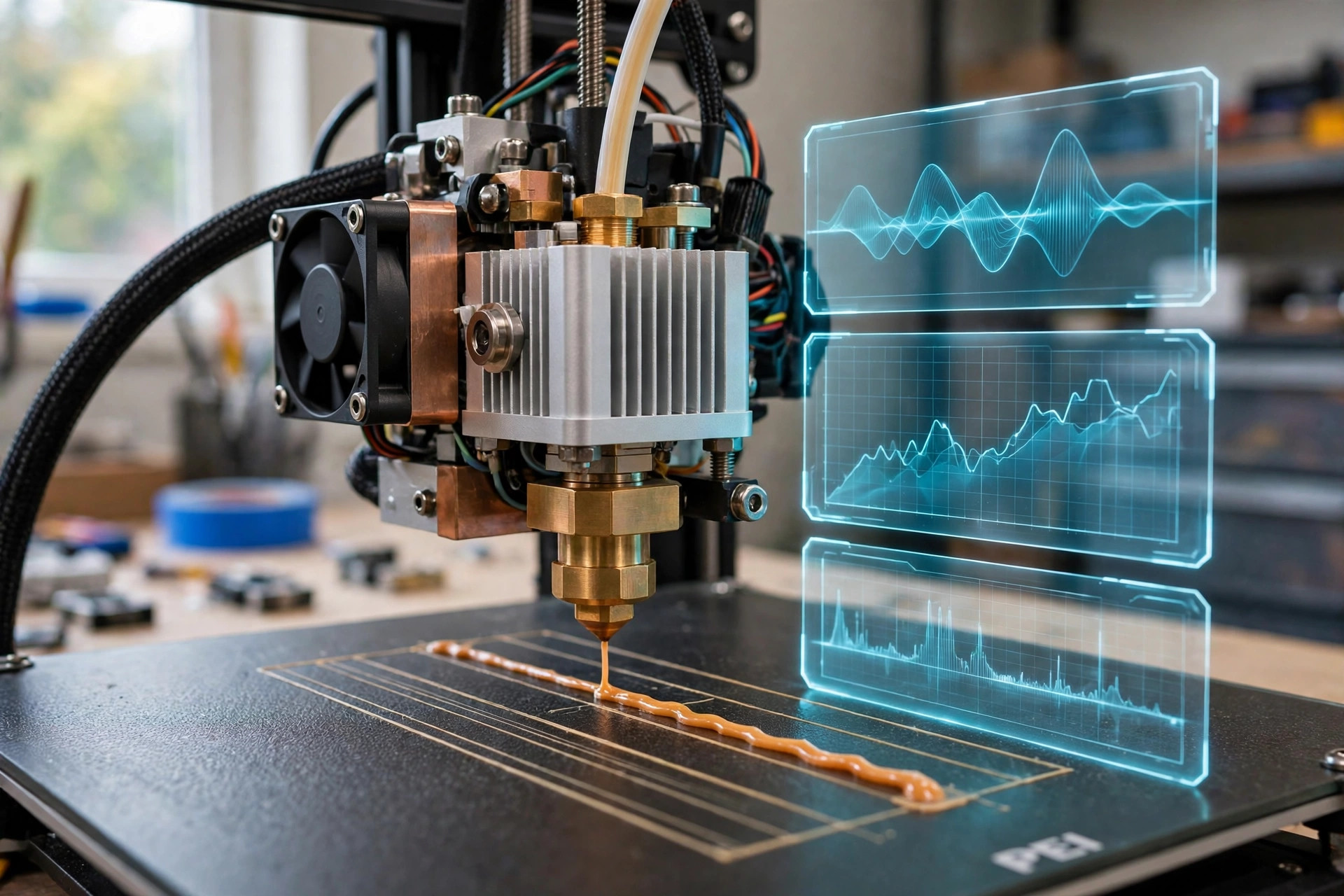
The preferred embodiment needs no modification to the hot end. A rotary encoder wheel rides the filament between the spool and the extruder, or on the extruder idler, and reports actual filament displacement independent of the stepper command. A current sensor on the extruder stepper driver, or a driver load measurement of the kind modern smart stepper drivers report, samples motor current at 1 kHz or faster and records current in the step band. A small microphone mounted near the extruder, shielded from cooling fan airflow, records extrusion sound. A scale with 0.1 gram resolution weighs printed calibration coupons. The operator enters filament material, nominal diameter, nozzle diameter, print temperature, print speed, and layer height once per spool, then updates only what changes. Direct drive and Bowden extruders share the same fusion logic; Bowden systems carry a longer filament path and therefore a larger baseline slip, which the per-printer baseline absorbs.
Step frequency sets the current analysis band. For a feed rate in millimeters per second and a steps-per-millimeter value set in firmware, step frequency equals feed rate multiplied by steps per millimeter. A typical direct drive extruder at 5 millimeters per second with 400 steps per millimeter steps at 2,000 steps per second, while a geared extruder steps faster for the same feed rate. The system records steps per millimeter at setup and tracks the step band from the live feed rate, rather than assuming one extruder behaves like another. That distinction matters, because a current rise that signals melt pressure in one extruder may be normal operating variation in another.
Two encoder placements are disclosed. In the first, a spring-loaded encoder wheel presses against the filament before the extruder and counts revolutions as filament passes, giving actual feed independent of gear slip. In the second, an optical or magnetic sensor watches the extruder idler rotation, which turns only when filament actually moves. Both placements measure the same quantity, actual filament displacement, and both fail safe in the same way: when the encoder reports nothing while the stepper is commanded to move, slip is total, which is a full jam rather than a partial clog.
2. Baseline Calibration Per Filament
Calibration runs over five reference coupons printed after a confirmed clean nozzle, or after a nozzle swap, for each new spool. A reference coupon is a small fixed-geometry print, for example a 20 mm hollow cube with two perimeters and no infill, printed at a stated temperature, speed, and layer height. From those coupons the system stores reference values for slip ratio, step band current root mean square, acoustic band energy between 2 and 8 kHz, and coupon mass. Medians, not means, define the baseline, so one coupon printed during a filament tangle does not move the reference.
Calibration also records the filament story. The operator enters measured filament diameter from calipers at several points along the spool, material type, and whether the filament is filled or unfilled. Where diameter is unknown, the system starts with the nominal diameter and widens its uncertainty bands until a measurement arrives. Diameter does not enter the obstruction index directly; it sets the expected feed behavior and the prior probability that a given drift is diameter variation rather than a clog.
Baseline slip is never zero in practice. A healthy direct drive extruder typically slips 1 to 3 percent, and a healthy Bowden extruder slips more, because the filament compresses slightly and the gear teeth bite and release. The system therefore treats slip as a baseline quantity with normal variation, not as an error that should read zero, and it scores only drift above that baseline.
3. The Obstruction Index
For each new reference coupon, and continuously for slip and current during ordinary prints, the system computes four normalized drift terms. Slip drift s is the rise in slip ratio above baseline, divided by 0.25, so 25 percentage points of extra slip scores 1.0. Current rise c is the fractional rise in step band current root mean square above baseline. Acoustic change a is the fractional rise in 2 to 8 kHz band energy above baseline. Mass deficit m is the fractional shortfall of coupon mass below commanded mass, divided by 0.20, so a 20 percent mass shortfall scores 1.0. Each term is clipped at 1.0 so no single channel can trigger a stop-and-clean call alone.
The obstruction index O combines them as O = 0.35s + 0.25c + 0.20a + 0.20m. A value near 0 means the printer behaves as it did with a clean nozzle. A value near 0.25 is the watch level, a value near 0.45 is the clean-soon level, and a value near 0.65 is the stop-and-clean level. Those thresholds are design choices, stated here so a builder can implement and then calibrate them, not measured performance claims. A 5-coupon rolling median smooths the index, because single coupons vary with ambient temperature and spool winding, and a coupon is excluded from the index when its temperature, speed, or filament differs from the reference recipe, rather than being corrected with a guessed adjustment.
Two physical arguments support the weighting. First, melt pressure drop through an orifice rises steeply as bore diameter falls, roughly with the inverse fourth power of diameter for a simple viscous flow model, so a small residue layer in a 0.40 mm bore produces a disproportionate pressure effect, while coupon mass responds more gradually as the extruder slips and grinds. Melt is shear thinning, so the fourth power exponent is approximate rather than exact, but the direction and the steepness both hold. Second, a genuine obstruction moves slip, current, acoustics, and mass together. A fault that moves only one channel is, on that evidence, probably not a clog, which is the core of the differential diagnosis in section 4.
A worked example shows the arithmetic. Suppose a clean baseline has slip 0.02, step band current 0.42 amperes root mean square, acoustic band energy at a reference level, and coupon mass matching commanded mass. A later coupon set shows slip 0.19, current up 38 percent, acoustic band energy up 55 percent, and coupon mass 12 percent below commanded mass. Then s = (0.19 minus 0.02) / 0.25 = 0.68, c = 0.38, a = 0.55, and m = 0.12 / 0.20 = 0.60. The index is O = 0.35 times 0.68 + 0.25 times 0.38 + 0.20 times 0.55 + 0.20 times 0.60 = 0.238 + 0.095 + 0.110 + 0.120 = 0.563, which sits at the clean-soon level and approaching stop-and-clean. The same arithmetic with only slip elevated, and current, acoustics, and mass at baseline, gives O = 0.238, below the watch level, which is why fusion matters: slip alone is not enough to condemn a nozzle.
4. Differential Diagnosis
The classifier assigns each drift pattern to one of the following classes, using the channel pattern plus the response to simple interventions:
- Partial clog: Slip up, current up, acoustic energy up, coupon mass down. Pattern persists across filaments and speeds, and improves after a cold pull or nozzle swap. This is the only class that moves all four channels together and then reverses with cleaning.
- Wet filament: Acoustic bursts broad across the spectrum, with audible popping as water flashes to steam in the melt zone, plus surface bubbles and stringing on the print. Slip and current stay near baseline, and the pattern follows the spool, resolving when the spool is dried, without any nozzle work.
- Filament diameter variation: Slip and mass deficit vary periodically with spool rotation or along the spool length, tracking caliper measurements of diameter. Current stays near baseline, and the pattern resets when a different spool is loaded.
- Heat creep: Slip rises late in long prints and after pauses, as heat travels up the heat break and softens filament above the melt zone. The pattern recovers after a cool-down, tracks ambient temperature and cooling fan state, and does not improve with a cold pull alone.
- Extruder gear wear: Slip up with visible ground filament dust at the gear, current near baseline, acoustic change small. Pattern persists after a nozzle swap, and resolves when the gear or idler tension is serviced.
- Bowden friction: Slip varies with print head position and bend radius of the feed tube, worst at the extremes of travel. Current rises only at those positions, coupon mass deficit is position dependent, and the pattern resolves when the tube is shortened, rerouted, or replaced.
- Nozzle bore wear: The opposite sign from a clog. An abraded bore widens, so coupon mass rises above commanded mass, line width grows, and current falls slightly as melt pressure drops. A clog call requires mass deficit, so bore wear cannot trigger one.
- First layer leveling error: Mass deficit and visual defects confined to the first layer, with later layers and reference coupons at baseline. The pattern tracks bed leveling and first layer height settings, not nozzle state.
Where the pattern is ambiguous between a partial clog and gear wear, the system prescribes a discriminating test before recommending a nozzle swap: extrude a fixed length of filament in free air, with the nozzle well above the bed, at a known temperature and speed, and weigh the extruded strand or measure its length against command. Free air extrusion removes bed backpressure and first layer effects, so slip and current at fixed resistance isolate the melt path. If free air extrusion still shows slip and current rise while a fresh spool behaves the same way, the nozzle leads. If free air extrusion is normal but printed coupons starve, the print setup side leads, and cleaning the nozzle is not the first action. A cold pull that brings out a clean, nozzle shaped plug, followed by coupons returning toward baseline, retrospectively confirms the clog call.
5. Clog Growth Model
Alongside the measured index, the system maintains a simple growth estimate that connects print history to expected bore narrowing. For extruded mass M in grams, a residue rate r in grams of deposit per gram extruded, and a temperature factor that rises when the nozzle runs above the material's recommended range, estimated deposit mass is M times r, scaled by the temperature factor. The residue rate is the least certain input, so the system carries it as a range per material class, low for unfilled PLA and PETG, higher for filled composites and for materials repeatedly held hot without extrusion, rather than a point value, and it learns the effective rate for a given printer and material by comparing predictions with the observed index change between cleanings.
As a scale check, narrowing a 0.40 mm bore to 0.34 mm raises the simple viscous pressure drop factor by (0.40 / 0.34) to the fourth power, about 1.92 times, before any slip occurs. That steep response explains why a clog that is barely visible in the orifice can still starve a print, and why current and slip are sensitive early indicators while coupon mass is the confirming one. The model is a planning aid for scheduling coupon checks, not a substitute for the measured index: when measurement and model disagree, measurement wins.
6. Staged Response and Verification
At the watch level, the system schedules a reference coupon at the next filament change and notes the drift in the print log. At the clean-soon level, it recommends a cold pull at the next convenient pause and a coupon afterward, and it warns before starting a print longer than a stated duration. At the stop-and-clean level, it recommends pausing the current print, performing a cold pull or nozzle swap, and printing two reference coupons before resuming long work. After cleaning, two coupons must return the index below the watch level for the call to count as confirmed; if the index stays high, the system reopens the differential diagnosis instead of repeating the same recommendation, since a persistent index after a nozzle swap points to gear wear, Bowden friction, or a feed path fault rather than the nozzle.
Claims
- A system for detecting partial nozzle obstruction in a fused filament fabrication printer, comprising: a filament feed encoder measuring actual filament displacement; a current sensor measuring extruder stepper current in the step band; a microphone measuring extrusion acoustic energy; a scale measuring printed coupon mass; and a fusion module that compares slip, current, acoustic energy, and coupon mass against a per-filament baseline and computes an obstruction index from the combined drift.
- The system of claim 1, wherein the fusion module computes slip ratio as commanded filament length minus actual filament length, divided by commanded filament length, using encoder displacement independent of the stepper command.
- The system of claim 1, wherein the fusion module computes the obstruction index as a weighted sum of slip drift, current rise, acoustic change, and coupon mass deficit, with each term clipped so no single channel alone triggers a stop-and-clean recommendation.
- The system of claim 1, wherein the fusion module establishes the baseline from median values over reference coupons printed with a clean nozzle at a fixed temperature, speed, layer height, filament, and nozzle diameter, and excludes non-reference coupons from the index.
- The system of claim 1, wherein the fusion module applies a rolling median to the obstruction index over multiple coupons, so single-coupon variation from ambient temperature and spool winding does not trigger a cleaning recommendation.
- The system of claim 1, further comprising a differential classifier that distinguishes partial clog from wet filament, filament diameter variation, heat creep, extruder gear wear, Bowden friction, nozzle bore wear, and first layer leveling error by the pattern of drift across slip, current, acoustic, and mass channels.
- The system of claim 1, wherein the differential classifier prescribes a free air extrusion test at fixed temperature and speed, and a cold pull with post-cleaning coupon verification, to isolate melt path drift from print setup drift before recommending a nozzle swap.
- The system of claim 1, further comprising a clog growth estimator that computes estimated deposit mass from extruded mass, a residue rate carried as a range per material class, and a temperature factor, and that updates the effective residue rate by comparing predictions with observed index change between cleanings.
- The system of claim 1, wherein the differential classifier treats coupon mass surplus, rather than deficit, as evidence of nozzle bore wear, so bore wear cannot trigger a clog recommendation.
- A method for detecting partial nozzle obstruction in a fused filament fabrication printer, comprising: recording filament feed slip, extruder stepper current, extrusion acoustics, and printed coupon mass for reference coupons; computing normalized drift in each channel against a per-filament clean-nozzle baseline; combining the drifts into an obstruction index; classifying the drift pattern against wet filament, heat creep, gear wear, Bowden friction, and bore wear patterns; and recommending and then verifying a cleaning based on the index and the post-cleaning recovery of the measured channels.
Prior Art References
- Marlin Firmware: Open source printer firmware documenting extruder motion control, steps per millimeter, and flow settings used as background for the extruder drive model in this disclosure.
- Klipper Firmware: Printer firmware documenting extruder kinematics and rotation distance calibration, used as background for the relationship between commanded rotation and filament feed.
- Duet3D Documentation: Documentation for filament monitors that measure filament motion independently of the extruder command, used as background for the feed encoder placement in this disclosure.
- RepRap Wiki, Fused Filament Fabrication: Community documentation of the filament melting and deposition process, nozzle geometry, and common print defects used as background.
- NIST Additive Manufacturing Program: United States measurement program for additive manufacturing processes, used as background for the measurement framing of this disclosure.
- LITF-PA-2026-214, Espresso Machine Scale and Pump Diagnostics: Prior LITF disclosure using multi-channel fusion against a post-service baseline with differential diagnosis; this disclosure differs by targeting nozzle obstruction in filament printers through feed slip, stepper current, acoustics, and printed mass.
- LITF-PA-2026-162, Refrigerator Compressor Health Prognostics: Prior LITF disclosure using acoustic and electrical signatures for appliance prognostics; this disclosure differs by fusing feed slip and printed mass with current and acoustics for a melt flow obstruction.
- 35 U.S.C. § 102: Conditions for patentability, including the printed publication and public availability provisions under which this disclosure is published.
Implementation Notes
This disclosure describes an untested design proposal; quantitative parameters are design choices awaiting field calibration, and no accuracy claim is made against opened nozzles or weighed deposits until that validation exists. A minimal prototype needs no hot end modification: a rotary encoder wheel pressed against the filament, a current sensing stepper driver or clamp sensor, a small microphone kept out of direct cooling fan airflow, and a 0.1 gram scale for coupons, all logged by a microcontroller or single board computer that already runs the printer.
Bring-up procedure: fit a new nozzle, print five reference coupons with one spool, and confirm that baseline medians are stable across the last three coupons. Then run the discriminating tests one at a time: a spool swap should move diameter related drift without moving current, a fan state change should move heat creep behavior without moving coupon mass on short prints, and a free air extrusion should give a clean hydraulic reference. If slip rises while current and mass stay flat, suspect gear wear or Bowden friction before suspecting a clog, since a clog moves all four channels together in this model.
Expected performance envelope (design targets for a validation program, not measured results): a stop-and-clean call should correspond to a post-cleaning index recovery below the watch level on at least 70 percent of calls, a false stop-and-clean rate below 1 in 5 calls on printers verified clean by nozzle inspection, and an obstruction index that rises monotonically across at least 80 percent of monitored clog intervals. Bowden printers will need separate slip baselines from direct drive printers, and filled filaments will need separate residue rate ranges from unfilled filaments, because their feed and fouling behavior differ.
Limitations: coupon mass depends on slicer settings, so a changed flow multiplier or infill pattern invalidates the baseline until recalibration, and operators who change settings frequently will generate fewer index points. A clog in the heat break above the nozzle, rather than in the orifice itself, may present more like heat creep than like a nozzle clog, and will need the cool-down discriminating test to separate. Acoustic sensing in a noisy workshop will need fan noise gating, since cooling fans dominate the same frequency bands when they run at full speed. This is a maintenance aid, not a safety device, and it does not replace manufacturer guidance or professional service for electrical, heater, or hot end faults.
The strongest counterargument is that a nozzle costs a few dollars and a cold pull takes minutes, so instrumenting a printer to decide when to clean may cost more than it saves for a hobbyist with one printer. That objection is fair for a single printer, and it is why the design leans on cheap add-on sensing, on early detection during long prints where a ruined print costs hours and a spool, and on fleet use, where one operator watches many printers and cannot inspect every first layer. If field data show that verified clean printers routinely cross the stop-and-clean threshold, the thresholds and weights in section 3 are wrong and should be recalibrated, not defended.