System and Method for Diagnosing Water Softener Failure Modes Using Regeneration-Phase Sensing
A water softener fails in nine ways that all look the same: hard water, a salt tank that looks full, and a valve running on schedule. The manual checks cost nothing; the wrong repair costs up to $400. This disclosure would fuse brine level, drain flow, outlet hardness, and inlet pressure across the regeneration cycle to name the cause while the softener runs.
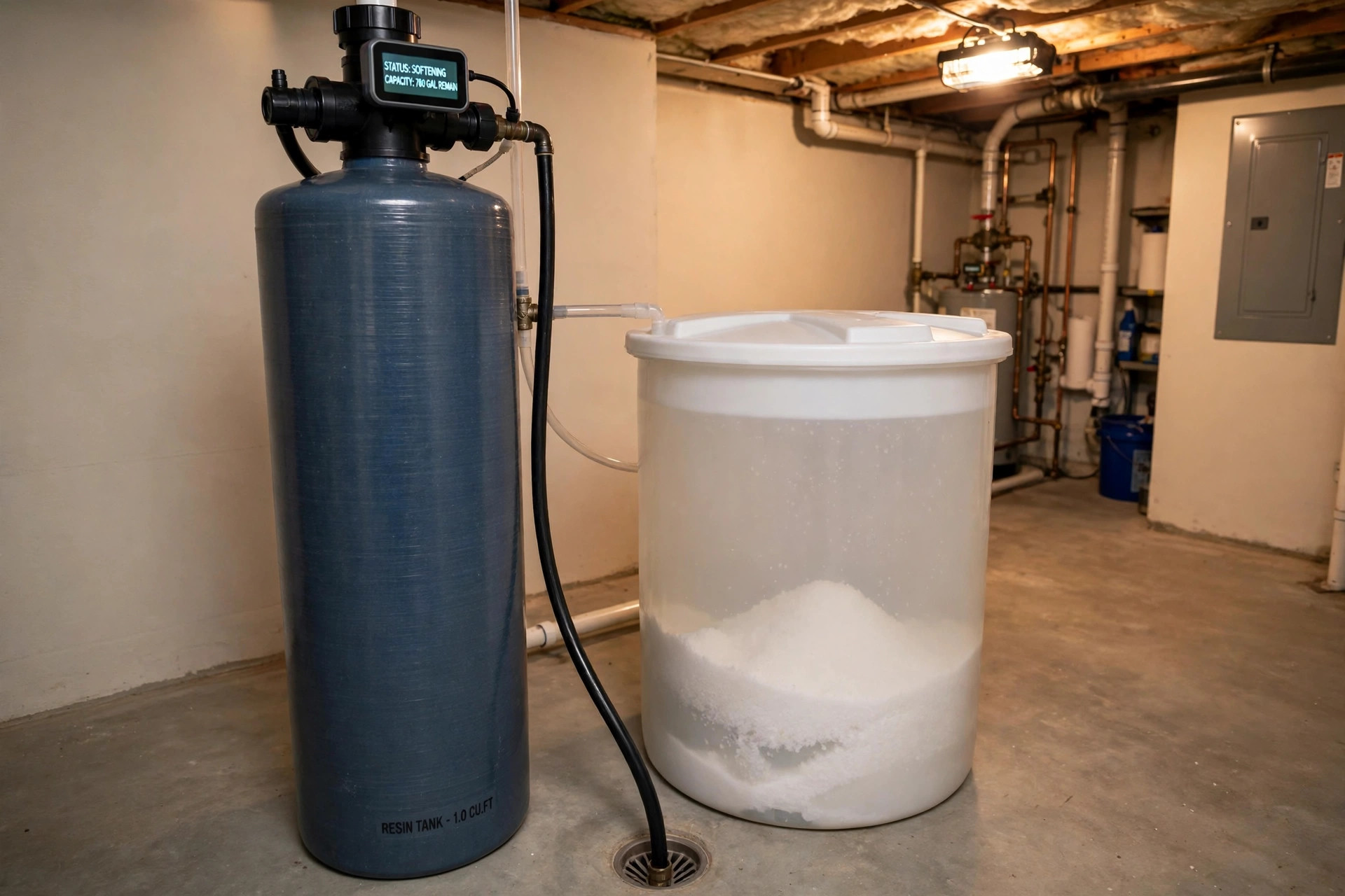
A broom handle and a test strip can diagnose your softener in thirty minutes. Nobody runs the test until the water has been hard for weeks. This disclosure would give the softener a voice.
Just want the 30-minute checks? Skip to What a Homeowner Can Do Now.
Share: X · Facebook · Copy link
Abstract
A proposed system would diagnose why a residential ion-exchange water softener stopped softening, rather than merely reporting that the water is hard. Four sensing channels would be fused across the regeneration cycle, plus the service flow total and the valve event log: brine-tank levels, water and solid salt, drain-line flow measured per regeneration phase, outlet hardness, and inlet pressure during the brine-draw phase. An edge diagnostic would compare the phase-resolved pattern against the signature of each failure mode: a salt bridge, a clogged brine injector, a drain restriction, exhausted or fouled resin, an open bypass, a valve or timer failure, low inlet pressure, a failed safety float, and a failed air check. The system would report a named cause with the repair that cause requires, and would track a softener effectiveness index, the gallons of soft water delivered per regeneration against the rated capacity, so a slow decline would be visible before the water turns hard.
Field of the Invention
This invention relates to residential water treatment, specifically to a diagnostic combination for ion-exchange water softening that distinguishes the nine failure modes in Table 1 for single-tank metered and time-clock residential softeners.
Background
Hard Water and the Softener
Hard water is water carrying dissolved calcium and magnesium, and it is common across much of the United States, where its severity follows the underlying geology: hardest in the Midwest, the Great Plains, Texas, and the Southwest, softest in the Pacific Northwest and parts of the Northeast and Southeast. The United States Geological Survey classifies hardness by concentration as calcium carbonate: soft at 0 to 60 milligrams per liter, moderately hard at 61 to 120, hard at 121 to 180, and very hard above 180. One grain per gallon equals 17.1 milligrams per liter. Hard water leaves scale on fixtures and inside water heaters, spots dishes, and makes soap lather poorly. A commonly quoted figure holds that 85 percent of American homes have hard water, attributed to the USGS, but that figure traces only to water-softener marketing sites citing one another: the USGS hardness page states classification ranges and a geological map, and no percentage of homes. This disclosure does not use the 85 percent figure. Hard water is common; silent failure is the problem.
A residential softener removes hardness by ion exchange. Service water flows down through a bed of resin beads, usually polystyrene crosslinked with divinylbenzene and carrying sulfonic acid groups that hold sodium ions. Calcium and magnesium in the water trade places with the sodium on the beads, and the water leaves soft. When the beads fill with hardness, the control valve runs a regeneration cycle, normally at 2:00 AM, in four phases. Backwash reverses flow upward through the bed for about 10 minutes, expanding and reclassifying it. Brine draw and slow rinse take about 60 minutes: a venturi injector draws saturated brine from the brine tank through the bed, so sodium takes its seats back and hardness goes to drain. Rapid rinse takes about 10 to 12 minutes. Brine refill takes 12 to 19 minutes depending on tank size, putting water back in the brine tank to dissolve salt for the next cycle. The listed phases sum to 92 to 101 minutes; with the valve's optional pause and second backwash, a full regeneration takes about two hours (one Fleck programming guide puts the base case at approximately 90 minutes).
The Fleck 5600SXT, a widely used residential control valve, ships with those defaults: backwash 10 minutes, brine draw 60, rapid rinse 10 to 12, brine fill 12 minutes for a 9-by-48 tank, 15 for 10-by-54, 19 for 12-by-52, day override 14 days, safety factor 15 percent. Usable capacity per cubic foot of resin rises with the salt dose, and published figures vary by source:
| Salt dose per cubic foot | Usable capacity, grains per cubic foot | Basis |
|---|---|---|
| 6 lb | about 20,000 | Nameplate |
| 8 lb | about 24,000 to 25,000 | Published figures vary |
| 10 lb | about 25,000 to 27,000 | Published figures vary |
| 15 lb | about 30,000 by nameplate; 26,513 measured in an NSF/ANSI 44 test | Nameplate vs NSF/ANSI 44 test |
The ranges in the table span published figures that disagree: the 10-pound range runs from 25,000 grains (ForeverPure) to 27,000 (Clack seminar excerpt, Ref. 23), and the 8-pound range from 24,000 (Clack, Ref. 23) to 25,000 (Glass Water).
Saturated brine is 26.4 percent salt by weight, about 2.65 pounds of salt per gallon of saturated brine, while one gallon of water added to the tank dissolves about 3.0 pounds of salt; the two figures use different denominators, a gallon of brine against a gallon of water added. The two figures agree once the volume growth on dissolution is counted: one gallon of water (8.34 pounds) plus 3.0 pounds of salt makes 11.34 pounds of solution, which at about 10.0 pounds per gallon of saturated brine occupies about 1.13 gallons, so 3.0 divided by 1.13 is about 2.65 pounds per gallon of brine.
In steady state the draw therefore pulls about 4.0 gallons of brine, not 3.5: 3.5 gallons of refill water plus 10.5 pounds of dissolved salt make about 3.97 gallons of brine, carrying about 10.5 pounds of salt out of the tank per cycle, the same amount the pile loses. One cited source states that a gallon of saturated brine weighs 10.74 pounds (Ref. 10), which implies a specific gravity of 1.29 against the established 1.20; that density figure is not relied on here. The brine line flow control is commonly 0.5 gallons per minute, so a 7-minute brine fill, an example efficiency setting rather than a Fleck default, admits about 3.5 gallons and dissolves about 10.5 pounds of salt per regeneration.
Resin lasts 10 to 15 years, less where the water carries iron or chlorine: resin makers recommend protecting resin whenever chlorine exceeds 0.5 parts per million, and sizing practice adds 5 grains per gallon of hardness for each part per million of dissolved iron. Municipal water typically carries about 0.5 to 2 parts per million of chlorine at the tap, against the EPA limit of 4, so the 0.5 threshold sits at the low end of normal; a household on well water with 1 part per million of iron would add 5 grains per gallon to its sizing.
How It Fails: Why Nine Failures Look Like One
The failure modes the repair guides rank first are documented in the manufacturers' own troubleshooting material and in independent repair guides, and the guides agree on the order to check them: salt bridge first, then injector, then drain, then resin. A salt bridge is a hard crust of packed salt that forms across the top of the brine tank, leaving a hollow space underneath, so the salt above the crust never reaches the water and no brine forms. It is the most common cause of sudden softener failure, and the check is a broom handle pushed down through the salt: firm resistance followed by a hollow space is a bridge. A clogged brine injector is the venturi nozzle and throat assembly that creates the suction to draw brine; plugged with debris or mineral scale, it draws nothing, and the resin never recharges. The Fleck service manual lists a plugged injector as the first cause when a softener fails to draw brine. The manual states 20 pounds per square inch as the valve's minimum operating pressure; some revisions state 25 pounds per square inch for effective regeneration, and section 5 gives both figures. This disclosure treats 20 pounds per square inch as the valve floor, not as an injector rating.
A clogged drain line or drain line flow control leaves regeneration water with nowhere to go, so the cycle fails and the brine tank can overfill. A failed safety float or air check has the same overfill symptom from the other direction: the tank keeps filling, or the draw pulls air instead of brine. Exhausted resin is the slow failure: beads that have lost exchange sites to age, iron fouling, or chlorine oxidation, so the softener regenerates normally and still delivers hard water. A re-bed by a professional runs 200 to 400 dollars, and a cubic foot of 10 percent crosslink resin cost 189 dollars as a part, both figures as of November 2026 from a single source, The Home Water Lab.
What makes these failures hard to tell apart is that they share a symptom and share a superficial sign. The symptom is hard water at the tap, and the sign is a softener that appears to be running: the valve cycles, the salt tank looks full, and nothing alarms. The Home Water Lab states the confusion plainly:
A salt bridge looks exactly like dead resin, and so does a clogged injector, a disconnected brine line, or a hardness setting someone changed years ago and forgot about.
The standard advice is a manual procedure that takes about thirty minutes and a hardness test strip: test the water first, confirm the symptom at the tap before opening the unit, then check the bypass valve, then push a broom handle through the salt, then remove and clean the injector, then check the drain line, and only then suspect the resin. That procedure works, and it is the procedure this disclosure automates. The failure it addresses is not that the procedure is unknown. It is that nobody runs it until the water has been hard for weeks, because nothing in the house reports the failure, and the damage hard water does in the meantime, scale inside the water heater and on fixtures, accrues silently. A vacation home or a rental has nobody to run the procedure at all.
What Exists Already
Existing art covers the pieces but not the diagnosis. Salt-level monitoring is patented art: EP 3981745 A1, a published application assigned to Culligan International Company (2022), discloses a Time-of-Flight sensor that measures the salt level in a brine tank without contact. Its background states the problem directly: salt bridges make the volume of salt seem greater than what is actually present, so a user visually inspecting the level often has no way to tell a bridge has formed. The application goes further than a level reading: it discloses taking salt-level readings once every operational cycle, preferably after brine draw, and generating a salt-bridge alarm when successive readings taken after successive cycles obtain similar level values. That is a cycle-resolved bridge alarm, and this disclosure concedes it. The application also discloses a brine-draw-failure alarm: paragraphs [0012] to [0013] state that a Time-of-Flight reading inconsistently shorter, meaning closer, indicates the water level in the brine tank is higher than the salt level, which indicates the brine has not fully drawn because of a leak or malfunction, and that repeated shorter readings indicate a brine draw failure. This disclosure concedes that alarm too.
What EP 3981745 does not do is distinguish a bridge from the other causes that also leave the pile frozen: a failed timer leaves successive readings similar from the start, and a clogged injector leaves them similar once the tank fills and salt stops dissolving, so its alarm fires on a frozen pile without naming which failure froze it. EP 3981745 infers a high water level from the same Time-of-Flight salt sensor, while the claimed system measures the brine water level directly, with a float or pressure sensor, and fuses it with per-phase drain flow and inlet pressure. EP 3981745's draw-failure alarm fires for any cause that leaves the water level high, injector, drain, or pressure, without naming which one.
Hardness breakthrough detection is patented art too: US 3,964,999 (1976) discloses detecting softener exhaustion by discriminating monovalent from divalent ions, and states the reason a simpler method fails, that softened water differs from hard water by only a slight conductivity difference, which makes exhaustion hard to detect by conductivity of the effluent alone. US 9,778,299 B2 (University of Texas, 2017) discloses a sensor for detecting hardness breakthrough by measuring a change in the conductivity of elongated cation-exchange material in contact with the treated water. The field is still moving: US 2025/0214870, published July 3, 2025, discloses slope-based resin-breakthrough identification using ion-selective electrodes at the softener outlet, and times regeneration to the measured breakthrough slope. It senses one channel, hardness, and does not fuse it with any other.
Smart softeners sold by GE, Culligan, Whirlpool, and Pentair report salt level and, in some models, water use, and Culligan's own controller names coarse error categories, Salt Bridging, Brine Blocked, Brine Overfill, No Brine In Tank, and valve motor faults, with dealer remote diagnostics behind them, while its Smart Brine Tank Probe is described as detecting bridging, eductor plugging, and overfilling. Those flags are coarse: an overfilled brine tank is a drain-restriction symptom and a valve-position fault is a valve-failure symptom, but no flag separates resin exhaustion from the brine failures, none is resolved by regeneration phase, and none tells the homeowner which repair the failure needs. The genuine gap is narrower than "no diagnosis exists": it is resin-exhaustion separation, phase resolution, and a homeowner-facing named cause with a repair. The Fleck 5600SXT service manual documents the failure modes and their fixes in a troubleshooting table, including that a plugged injector, a plugged drain line flow control, and a failed safety float each produce distinct symptoms, but the manual is a document for a technician with the valve open, not a system that watches the softener run. No patent, product, or publication found in the search described below fuses brine-level trajectory, per-phase drain flow, outlet hardness, and inlet pressure during the brine-draw phase to distinguish a salt bridge from an injector clog from a drain restriction from resin exhaustion, with the bypass, timer, low-pressure, float, and air-check failures included. That narrower combination, the phase-resolved diagnostic fusion, is the gap this disclosure addresses.
The Search
The search behind the novelty statement covered US and European patent publications through November 2026, queried through Google Patents and the EPO publication server with terms combining water softener with salt bridge, brine injector, drain flow, hardness breakthrough, ion-selective electrode, and fault diagnosis. It also covered manufacturer service documentation for the Fleck 5600SXT and the Culligan HE Twin, smart-softener product documentation from GE, Culligan, Whirlpool, and Pentair, Water Quality Association guidance, and independent repair guides. The combination it found nothing for has six elements:
- brine-tank water level and solid salt level tracked through the regeneration cycle rather than read once, the salt level measured without contact, with a lid-state switch reporting whether the brine tank lid is open;
- drain-line flow measured separately in each regeneration phase, so backwash flow and brine-draw flow are known independently;
- outlet hardness measured continuously in service, so the gallons of soft water delivered between regenerations are known, not estimated;
- inlet pressure measured during the brine-draw phase, against the 20 pounds per square inch minimum operating pressure the Fleck valve specifies;
- an edge diagnostic that matches the phase-resolved pattern across those channels to a named failure cause, with a confidence and the repair that cause requires; and
- a softener effectiveness index, the gallons delivered per regeneration against the rated capacity, tracked across regenerations so a slow decline is visible before the water turns hard.
One concession is needed on scope. Non-contact salt-level sensing is patented art, cycle-resolved salt-bridge alarming is disclosed in EP 3981745 A1, hardness breakthrough sensing by cation-exchange conductivity and by ion-selective electrode slope is patented art, the Fleck troubleshooting table documents the failure modes and their fixes, Culligan's controller names coarse error categories, and the thirty-minute manual diagnostic procedure is published in repair guides. This disclosure does not claim salt-level sensing, bridge alarming, hardness sensing, a troubleshooting table, an error code, or the manual procedure. The distinction rests on the narrower combination: the four channels fused across the regeneration phases, with the phase-resolved signatures that separate causes which present the same symptom and the same superficial signs. A salt-level sensor alone cannot tell a bridge from a clogged injector, because EP 3981745's own alarm would fire for either. A hardness sensor alone cannot tell a bridge from exhausted resin, because both deliver hard water. Only the pattern across the phases separates them, and no existing system reads that pattern.
Detailed Description
This section describes a proposed system. No prototype exists. Every threshold, rate, and cost figure in it is a design target, not a measured result. Conditional language is used deliberately throughout.
1. System Overview
Five parts would make up the system. A sensing unit mounted on the softener would carry the brine-tank level sensor, a lid-state switch on the brine tank lid, the drain flow sensor, the outlet hardness sensor, the inlet pressure transducer, and the service flow totalizer tap. An edge diagnostic unit in the sensing unit would read those channels through each regeneration phase, compare the phase-resolved pattern against the failure-mode signatures in section 6, and output a named cause with a confidence. A display would show the softener state, the effectiveness index, and the repair for the diagnosed cause.
A valve interface would read the control valve event log, which phases ran and for how long, either from the valve controller directly or inferred from the drain flow and pressure channels, with the inference validated as section 5 describes. A household gateway, optional, would carry the diagnosis to the homeowner by message and keep the regeneration history. No water would be added or removed by the system, no plumbing would change, and no cloud connection would be needed for the diagnosis itself: the edge unit would name the cause in the moment, on the device, and the gateway would add only the history and the remote message.
A configuration input would receive the feed hardness value, the iron concentration value, the programmed salt dose, and a resin-replacement event, so the diagnostic knows the water it is treating and when the resin was last changed.
2. Brine-Tank Sensing: Two Levels, Not One
The brine tank would carry two level measurements, because one level cannot separate the failures. A Time-of-Flight sensor mounted under the brine tank lid would measure the height of the solid salt pile, the sensing approach EP 3981745 A1 discloses for salt-level monitoring; an ultrasonic sensor would be an alternative embodiment. A second measurement, a float or a pressure sensor at the tank bottom, would measure the brine water level, and would be a contact measurement, unlike the salt level. The two levels would move differently in normal operation and in each failure, and the difference would be the signal. In normal operation the salt pile would fall steadily, about 10.5 pounds per regeneration for a one-cubic-foot unit on a 7-minute brine fill at a 0.5 gallon per minute brine line flow control, while the water level would cycle. It would fall during the 60-minute brine draw as brine is pulled to the resin tank, then rise during brine refill as fresh water is admitted to dissolve salt for the next cycle.
The edge unit would record both levels at four points in every cycle: at cycle start, at the end of brine draw, at the end of rapid rinse, and at the end of refill. The four-point trajectory would be the measurement, not any single reading: a salt pile that never falls across three regenerations would be a different fact from a salt pile read once, and a water level that never falls during brine draw would be a different fact from a water level read at rest.
Salt bridging and salt mushing would be read from the salt pile trajectory. A bridge is a hard crust across the tank with a void underneath; the salt above the crust never reaches the water, so the pile height would stay constant while regenerations draw brine from below, and the pile would stop falling even as the water level keeps cycling. Mushing is the wet counterpart, fine salt and impurities settling into a sludge at the tank bottom that the water cannot dissolve, which would also freeze the pile height while the brine concentration falls. The sensor would report the pile height in centimeters with a resolution target of 5 millimeters, and the diagnostic would flag a bridge when the pile height changes by less than the resolution across three consecutive regenerations while outlet hardness rises. That three-regeneration rule is a design target, chosen so a single missed reading cannot declare a bridge.
The water level would carry the bridge-versus-injector distinction, not a second bridge signal: in a bridged tank the water level would still fall during draw, because brine already in the tank below the crust is drawn normally, while in an injector clog the water level would not fall at all, because no brine leaves the tank. The disclosure does not claim a brine concentration sensor; the pile trajectory plus the water level trajectory is the bridge measurement. A lid-state switch on the brine tank lid would report whether the lid is open, so the rejection rule in section 10 can be enforced.
3. Drain Flow: One Sensor, Four Phases
A hall-effect flow sensor on the drain line would measure flow separately in each regeneration phase, because the phases would isolate different parts of the machine. Backwash flow would isolate the drain path. During backwash the valve would send service water upward through the resin bed and out the drain at the drain line flow control rating. A backwash flow below 70 percent of its learned baseline would mean the drain is restricted, whatever else is wrong. Brine-draw flow would isolate the venturi. During the 60-minute brine draw the flow through the drain would be the slow rinse flow, about 0.5 to 1.0 gallons per minute per cubic foot of resin, driven by the injector. A brine-draw flow below 50 percent of baseline, with a normal backwash flow, would mean the injector is not pulling, not that the drain is blocked.
Rapid rinse flow would re-check the drain path at a higher rate. Refill would admit no drain flow at all, so any drain flow during refill would mean a valve seal is leaking. The sensor would integrate flow per phase and report gallons per phase, with a target accuracy of 5 percent, and the edge unit would compare each phase total against the baseline learned in the first three regenerations after installation, as section 8 describes. Phase-resolved flow is what would separate the injector clog from the drain restriction: both would leave the brine tank full after a cycle, but only the drain restriction would also starve the backwash.
4. Outlet Hardness: The Outcome Channel
Outlet hardness would be measured continuously in service by a calcium-selective electrode or by a cation-exchange conductivity cell of the kind US 9,778,299 B2 discloses, mounted on the softener outlet. Soft water in this disclosure means outlet hardness below 1 grain per gallon. The measurement would be reported in grains per gallon, and the edge unit would record three values per service run: the hardness immediately after regeneration, the hardness at breakthrough, and the gallons delivered between them. The hardness immediately after regeneration would test whether the regeneration worked at all: a softener that leaves the cycle delivering 8 grains per gallon never recharged, whatever the phase readings say. The gallons to breakthrough would test whether the resin still holds its rated capacity. A one-cubic-foot unit on a 10-pound salt dose with a usable capacity setting of 24,000 grains, the efficiency setting a dealer would program, should deliver about 2,400 gallons before breakthrough at 10 grains per gallon of feed hardness, or 2,040 gallons before the next regeneration once the valve's 15 percent reserve is held back.
The 24,000-grain setting is a conservative programmed derate, below the 25,000-to-27,000 published capacity at a 10-pound dose in the table in Background. A unit delivering 2,000 gallons would be healthy; a unit delivering 900 gallons on the same settings would have lost more than half its capacity, and the loss would be the resin signal.
The hardness channel would also carry the bypass signal: if outlet hardness equals feed hardness immediately after a regeneration, while every regeneration phase ran normally, the water would be bypassing the resin bed, and the cause would be the bypass valve position or a plumbing error, not the softener. Simple conductivity of the effluent would not be used as the hardness measurement, because US 3,964,999 establishes that softened water differs from hard water by only a slight conductivity difference; the calcium-selective or cation-exchange measurement is the channel, and its drift and calibration limits are stated in section 10 and in Limitations.
A worked example, with illustrative numbers: a household of four using 70 gallons per person per day, 280 gallons a day, on 10 grains per gallon feed water, with a one-cubic-foot softener set to a 10-pound salt dose and a usable capacity setting of 24,000 grains. That setting should deliver 2,400 gallons between regenerations before breakthrough, 24,000 grains divided by 10 grains per gallon. The valve holds back a 15 percent reserve, 360 gallons, leaving 2,040 gallons delivered before the next regeneration, or about every 7 days at 280 gallons a day. The brine fill behind that dose would be 7 minutes at a 0.5 gallon per minute brine line flow control, admitting 3.5 gallons, each gallon dissolving about 3.0 pounds of salt, about 10.5 pounds per regeneration against a programmed dose of 10 pounds; the half pound is rounding in the dose setting.
If that household's system regenerates on schedule, about every 7 days, but the water tests hard after about 3 days, 840 gallons, the gallons to breakthrough have fallen to about 840, which is 41 percent of the 2,040-gallon rating, so the capacity has fallen by about three-fifths. The diagnostic would name resin exhaustion or fouling, provided the phase readings are normal. The example assumes the metered valve this disclosure uses as its reference: a metered valve regenerates when the programmed volume is consumed, so exhausted resin shows as mid-cycle breakthrough, not as more frequent regeneration. On a time-clock valve set to regenerate every 3 days regardless, the same capacity loss would show as hard water after every cycle instead. If instead the system regenerates on schedule but the water tests hard the morning after, and the brine water level never fell during the draw phase, the diagnostic would name the injector. Those numbers are design targets, pending measurement.
5. Inlet Pressure and the Valve Event Log
Inlet pressure would be measured by a transducer on the softener inlet, sampled through the regeneration cycle and in particular during the brine-draw phase. The injector is a pressure device, and the valve itself has a pressure floor. The Fleck service manual states 20 pounds per square inch as the valve's minimum operating pressure, and its installation section states 25 pounds per square inch as the minimum for the valve to operate effectively. A home whose inlet pressure sags below that floor during the 2:00 AM draw would fail to draw brine for a reason that has nothing to do with the injector. That sag can happen when a well pump cycles or a neighbor draws.
Incoming service pressure is typically 45 to 60 pounds per square inch under the EPA WaterSense recommendation, and most plumbing codes require a regulator above 80, so a reading below 20 would be far outside normal service, not a borderline call. The pressure channel exists to prevent a false injector diagnosis: a brine draw that fails while inlet pressure reads below 20 pounds per square inch would be reported as low inlet pressure, not as a clogged injector. Because the transducer would sample through the whole cycle, the diagnostic would also know whether the sag spans backwash: a sag confined to the draw phase would leave backwash flow normal, while a sag spanning the cycle would depress backwash flow too, and the signature table in section 6 records that distinction. The valve event log would record which regeneration phases ran and for how long, read from the valve controller where the valve exposes it, or inferred from the drain flow and pressure channels where it does not. The log would carry two failure signals of its own: a regeneration that never starts, which would mean the timer, meter, or control board failed, and a regeneration that starts but never advances past backwash, which would mean the valve drive or piston stuck. A softener that has logged no regeneration in 14 days, the Fleck day override default, while water use continues, would be reported as a valve or timer failure, not as resin exhaustion, because the resin never had a chance to recharge.
Where phase boundaries are inferred from the drain flow and pressure channels rather than read from the valve, the inference would be circular if left unchecked: the same channels the diagnostic scores would also define the phases. The disclosure would break that circle in two ways. First, the inferred phase sequence would be checked against the valve's programmed durations, backwash about 10 minutes, brine draw about 60, rapid rinse 10 to 12, brine refill 12 to 19, and against the programmed order of the phases; a flow pattern that matches no programmed phase sequence would not be labeled as a phase at all.
Second, a stuck valve that never advances would produce a steady flow pattern with no phase transitions, and the diagnostic would report that as a valve failure rather than scoring it as a phase. Phase labels would therefore be validated against the program before any signature is scored, and an unvalidatable phase sequence would suspend diagnosis under the rejection rules in section 10.
6. Edge Diagnostic: The Signature Table
Why nine failures look like one, in a table.
The edge diagnostic would match the phase-resolved pattern against the signature of each failure mode, and would output the best-matching cause or causes with a confidence and the repair each cause requires. The signatures are the claimed combination, and they are stated as a table so the discrimination is inspectable rather than a black box. A pattern matches a signature when every value stated in that signature's row holds: no single channel names a cause, and a cause would be reported only when its full signature matches. A blank cell imposes no requirement, and a conditional cell is read against its stated condition. The dependent claims recite the discriminating subset of each signature, the cells that separate that cause from its nearest neighbor; the table states the full signature, and the edge diagnostic would apply the full signature.
Confidence would be computed only over the threshold-type cells of the matched signature: a threshold-type cell is a cell stating a numeric one-sided limit, below or above a stated value. For each such cell, the margin would be the measured value's distance past its threshold divided by the threshold, capped at 100 percent, the distance measured as the threshold minus the measured value for a below-type threshold and as the measured value minus the threshold for an above-type threshold, and the reported confidence would be the smallest such margin. Cells that state "Normal," equality, a band, zero flow, or no change would contribute only a pass or a fail, not a margin. Confidence here is a margin, not a probability: it states how far each measured value sits past its threshold, not the likelihood the diagnosis is right. The display would show the margin as a band, low, moderate, or strong, with the percentage kept only in the raw phase readings for inspection. The bands are design targets: low below 25, moderate from 25 to 75, strong above 75, on the capped 0-to-100 margin scale.
Table 1: Failure-mode signatures. Each row is one cause; each column is one channel. A cause is reported only when every cell in its row holds. Blank means the channel is not part of that signature. gpg = grains per gallon.
| Failure mode | Salt pile across 3 regens | Brine water level during draw | Brine level after refill | Drain flow: backwash | Drain flow: brine draw | Inlet pressure during draw | Outlet hardness after regen | Gallons to breakthrough |
|---|---|---|---|---|---|---|---|---|
| Salt bridge or mushing | Unchanged, within 5 mm | Falls normally | Normal | Normal | Normal | Normal | Rises after regen, above 1 gpg | Near zero after first failed regen |
| Clogged brine injector | Falls normally | Does not fall | Normal | Normal | Below 50% of baseline | At or above 20 psi | Rises after regen, above 1 gpg | Near zero |
| Drain restriction | Falls normally | Falls slowly or not at all, below 50% of baseline fall | Normal | Below 70% of baseline | Low, below 50% of baseline | Normal | Rises after regen, above 1 gpg | Declining across regens |
| Exhausted or fouled resin | Falls normally | Falls normally | Normal | Normal | Normal | Normal | Soft at once, below 1 gpg, then breakthrough early | Steadily shrinking over regens |
| Bypass open | Falls normally | Falls normally | Normal | Normal | Normal | Normal | Equals feed hardness at once | Zero |
| Valve or timer failure | Unchanged, within 5 mm | Unchanged | No flow across the 14-day day-override interval | No flow | Equals feed hardness after remaining capacity exhausts | Zero, no regen logged | ||
| Low inlet pressure | Falls normally | Falls slowly, below 50% of baseline fall | Normal | Low if the sag spans backwash, else normal | Low, below 50% of baseline | Below 20 psi | Rises after regen, above 1 gpg | Declining across regens |
| Failed safety float | Falls normally | Falls normally during draw | More than 10% above baseline | Normal | Normal | Normal | Rises after regen, above 1 gpg | Declining across regens |
| Failed air check | Falls normally | Does not fall during draw | Normal | Normal | Normal, rinse water still flows | Normal | Rises after regen, above 1 gpg | Declining across regens |
The qualitative terms in the table have quantitative definitions. "Normal" means within the baseline ratios in section 8: backwash flow at or above 70 percent of baseline, brine-draw flow at or above 50 percent, brine water level fall at or above 50 percent, and inlet pressure at or above 20 pounds per square inch. Normal for the brine level after refill means within 10 percent of baseline. "Falls normally" for the salt pile means a fall consistent with the programmed salt dose, as in the section 4 example. For a typical 18-inch-diameter brine tank, the programmed dose is about 2 to 3 centimeters of pile height, so a 5-millimeter resolution is about a fifth of one regeneration's fall, and the figure scales with tank diameter. "Rises after regen" means outlet hardness above 1 grain per gallon in the first service run after a regeneration.
"Breakthrough early" means outlet hardness rises above 1 grain per gallon before the rated gallons per regeneration are delivered. "Declining across regens" means the softener effectiveness index falls by more than 0.05, in absolute index points, per regeneration across five regenerations, scored in the onset window, the first cycles after the failure begins; a failure that stabilizes below 50 percent of rated gallons across three consecutive regenerations would also match, as a stable reduced capacity. "Near zero" for gallons to breakthrough means below 10 percent of rated gallons, the softener delivering essentially no soft water before hardness returns; "Zero" means no soft water delivered at all. The bridge row's "after first failed regen" marks that stored brine below the crust still recharges the resin once; the injector row's "Near zero" applies from the first failed cycle. "Unchanged," "Does not fall," and "No flow" are read literally. The gallons column records severity, not cause: a severe drain restriction or a total draw failure from low pressure would also read near zero, and the cause is fixed by the flow and pressure cells.
"Steadily shrinking" for resin means the softener effectiveness index falls by the decline rule in section 7, while every phase reading stays normal, which is the only pattern in the table where the phases run clean and the capacity still falls. The failed-safety-float signature is confirmed by a brine water level more than 10 percent above baseline after refill, a refill-phase reading, as the table states. The float row's decline has a mechanism: the overfill dilutes the brine, so each regeneration delivers less salt. For any failure that stops brine draw, the pile would fall normally until the tank fills and then stop dissolving; the table states the pile trajectory in the first cycles after the failure begins, and the water-level and flow cells are the primary discriminators.
The pile arithmetic closes once the volume growth on dissolution is counted: the pile falls by the salt dissolved, about 10.5 pounds per regeneration, and the drawn brine carries the same amount out of the tank. The reason is the volume growth: 3.5 gallons of refill water plus 10.5 pounds of dissolved salt make about 3.97 gallons of brine, and 3.97 gallons at 2.65 pounds per gallon is about 10.5 pounds. The steady-state draw volume is therefore about 4.0 gallons, not 3.5.
The table also states what the diagnostic would not do. A salt bridge and a clogged injector would both leave hard water, and both would leave the salt pile looking full on a casual look. But they would differ in the brine water level during draw and in the pile trajectory. The injector clog would leave the level flat while brine exists in the tank, and the pile falling normally in the first cycles. The bridge would leave the pile frozen across cycles while the water level falls normally. The timing matters: an injector clog would freeze the pile too, once the tank fills and salt stops dissolving, so a pile frozen across all three cycles would point to a bridge, while a pile that falls and then stops would point to a clog that formed during the window. A drain restriction and an injector clog would both leave the brine tank full after a cycle, but they would differ in backwash flow: only the drain restriction would starve the backwash. Resin exhaustion and a bridge would both show declining gallons to breakthrough, but they would differ in every phase reading: exhaustion would run a normal regeneration and still fail. A bridge would fail to make brine at all, and the two would differ in the hardness reading at once after regeneration, soft for exhaustion and hard for a bridge.
Low inlet pressure and an injector clog would both show low brine-draw flow, but they would differ in the pressure channel, which is why the pressure channel exists. A failed safety float and a drain restriction would both overfill the brine tank, but they would differ in backwash flow, normal for a float failure and starved for a restriction. A failed air check and a clogged injector would both leave the brine level flat during draw, but they would differ in brine-draw flow: the air check would still pass rinse water to the drain, so draw flow would stay normal, while the injector would pass almost nothing. Both rows are scoped to one failure direction: the float row covers a float that fails open and overfills, and the air-check row covers a check that fails closed and draws air. A float that fails closed and starves refill would present like an injector clog, and a check that fails open is unmodeled.
When two signatures hold at once, the diagnostic would report both causes in order of confidence and would say the pattern is ambiguous rather than picking one: a softener with a bridge and a clogged injector is a real possibility.
A confident wrong answer is worse than an honest pair.
When no signature holds, the diagnostic would report unknown cause with the raw phase readings, rather than guessing.
7. Softener Effectiveness Index
The diagnostic would track a softener effectiveness index, defined as the gallons of soft water delivered per regeneration divided by the rated gallons per regeneration for the installed resin volume, salt dose, and iron-adjusted feed hardness, the feed hardness increased by 5 grains per gallon for each part per million of dissolved iron, the sizing practice in Background. The rated gallons per regeneration would be computed from the capacity table in Background: usable grains at the programmed salt dose, divided by iron-adjusted feed hardness in grains per gallon, minus the reserve. A new softener should read near 1.0. In plain terms, an index of 1.0 means the softener delivers its rated gallons; 0.8 means one gallon in five of rated capacity is gone; 0.7 means nearly a third is gone. An index that falls to 0.7 would mean the softener delivers 30 percent less soft water per regeneration than rated. An index that falls by more than 0.05, in absolute index points, per regeneration across five regenerations would count as a steady decline, meaning the resin is losing exchange sites, whatever the hardness reading on any single morning says.
The index would be reported after every regeneration, with its five-regeneration trend, so a slow decline would be visible before the water turns hard. The index would be suspended, not reported, while any rejection rule in section 10 holds, because an index computed from a regeneration that never drew brine measures the brine failure, not the resin.
8. Baseline Learning: Three Regenerations
No two installations share the same drain flow, brine draw rate, or inlet pressure, because drain line flow controls, brine line flow controls, pipe lengths, and municipal pressure all vary. Its baseline would therefore be learned, rather than shipped as fixed thresholds: the first three regenerations after installation would be recorded as the baseline, provided outlet hardness after each of those three reads below 1 grain per gallon, which establishes that the softener was healthy when the baseline was taken. At a 7-day regeneration interval, learning the baseline would take about 21 days, and the display would say the baseline is still learning until then, showing the state as unverified, not healthy, and reporting no effectiveness index until the baseline is set. Every later phase reading would be compared against that baseline as a ratio, not an absolute: backwash flow below 70 percent of baseline, brine-draw flow below 50 percent of baseline, and brine water level fall below 50 percent of baseline would each count as a failed phase, with those percentages as design targets.
A baseline learned from a softener that was already failing would poison every later comparison, so the system would refuse to set a baseline until three consecutive regenerations each deliver soft water, and would say so on the display until the baseline is set. If the homeowner replaces the resin, cleans the injector, or changes the salt dose, the baseline would be reset and relearned over the next three healthy regenerations.
9. Display, Gateway, and Fleet Learning
The display would show one state per softener: healthy, with the effectiveness index and the gallons remaining before the next regeneration; or a named cause, with the confidence shown as a margin band, low, moderate, or strong, rather than a percentage or a probability, the repair, and the phase readings behind it. To guard against false confidence, the display would also show the date of the last independent water test and prompt the homeowner to test with a strip monthly, and would show a calibration-due state when the hardness sensor is past its calibration interval. A softener past its calibration interval or without an independent test in 90 days would show as unverified, not healthy. Ninety days is a design target, chosen so a single missed monthly test does not flip the display. The repair text would follow the manufacturer procedure for that cause: break up the bridge with a broom handle for a salt bridge, and remove and clean the injector screen, nozzle, and throat with warm water for a clogged injector. The repair text would say: check the drain line and flow control for a drain restriction, close the bypass for an open bypass, and call for a re-bed for exhausted resin.
The gateway, where installed, would carry the diagnosis to the homeowner by message and keep the regeneration history: gallons per regeneration, effectiveness index trend, and every diagnosed cause with its date. Across homes, an opt-in fleet service would correlate failure modes with water chemistry and valve model, so a household on 15 grains per gallon well water with iron learns from other households on the same water, and a valve model with a recurring injector fault is visible as a pattern rather than a series of isolated surprises.
The fleet service would need privacy limits stated in the disclosure itself, because the data it collects can identify a household even without a name on it. It would receive only the failure mode, the valve model, a feed hardness value and an iron concentration value, and the phase readings, with household identity replaced by a rotating pseudonym, one that rotates monthly rather than staying fixed per household. The pseudonym would be derived on-device from a household secret the gateway never transmits, with no server-side household-to-pseudonym table, so the operator would hold no key linking one rotation's pseudonym to the next. The household secret would be generated on the gateway at install and stored on the gateway; if the gateway is replaced or reset, the secret is lost and the pseudonym rotates, which is fine for privacy. Within a monthly rotation, records from the same household can still be linked, and phase readings plus regeneration timing and gallons are themselves quasi-identifiers. Feed hardness and valve model can still identify a household to someone who knows the local water. A rotating pseudonym slows correlation without preventing it, so pseudonymity here means no household name or address, not no information about the household.
Before upload, the gateway would minimize the payload on-device, stripping timestamps and per-regeneration volumes, so the fleet service receives no per-regeneration history. Uploads would be batched on a fixed daily schedule, so arrival time carries no regeneration cadence. The regeneration history itself would be stored locally on the gateway, and only the minimized payload would leave the home. The locally stored regeneration history is visible to anyone with access to the gateway, so the vacancy inference applies to local access as well as to the fleet, and in a rental the landlord's access to the local history is not governed by the tenant-objection rule. The fleet service would neither sell nor transfer household records to a third party, and that commitment would be stated at opt-in. That commitment does not cover compelled disclosure, such as a subpoena, or a sale of the operator itself. Water-use patterns belong to everyone in the household, including tenants, so opt-in would require notice to all occupants. Notice would be the homeowner's attestation on the opt-in screen, recorded with the opt-in; the system does not itself verify that every occupant was told. Opt-in would be performed by the homeowner, not the dealer or installer, on a screen naming the fleet operator and the data sent. The dealer or installer would have no access to the diagnosis or the locally stored history after install unless the homeowner grants it. A tenant's objection would withdraw the household, and an objection or withdrawal would be recorded and would block re-enrollment until a fresh opt-in by the homeowner after 90 days.
The fleet service would be run by the manufacturer or a named operator, records would be stored encrypted at rest and in transit, with the operator holding the keys, and retained for 24 months, two annual cycles, and a household could withdraw opt-in at any time, after which its records would be deleted, not merely anonymized. Encryption with operator-held keys protects the records against an outside breach, not against the operator itself, which can read the records it stores. On withdrawal, the fleet service would issue a deletion receipt stating the records deleted, and deletion would cover backups and processors within 30 days; no third-party audit of deletion is specified. Deletion would cover the household's records and future aggregates; aggregates already published before withdrawal would not be retracted, and the household would be told this at opt-in.
Two further risks would be disclosed to the household at opt-in: water-use patterns in the regeneration history can show when a home is empty, which is a vacancy inference, and a small fleet, a single valve model on a single street's water, can make one household stand out even behind a pseudonym. The fleet service would therefore report only aggregate failure likelihoods per model and per water chemistry, never per-household histories, and would suppress any aggregate built from fewer than ten households in that model-by-chemistry slice, ten being a design target for the smallest publishable aggregate.
10. Scoring Rejection Rules
Diagnosis would be suspended when the data cannot support it:
- a salt-bridge finding would be rejected while the brine tank lid is open, because the Time-of-Flight sensor reads the lid, not the salt;
- hardness readings would be rejected while the hardness sensor reports a calibration fault or while the sensor has been dry, because a calcium-selective electrode that has dried out would read nonsense until it is reconditioned;
- a resin-exhaustion finding would be rejected for the first three regenerations after a re-bed, because new resin has no history to decline from;
- an injector finding would be rejected while inlet pressure reads below 20 pounds per square inch, the valve minimum operating pressure, and low inlet pressure would be reported instead, as section 5 states;
- all findings would be rejected while the softener is in bypass for maintenance, while the household is on vacation with no water use, and for 24 hours after salt is added to the brine tank, while the pile settles; the vacancy inference behind the vacation rule would be computed on-device and would never leave the home;
- all findings would be rejected while an inferred phase sequence fails the validation in section 5, because an unvalidatable phase cannot be scored; and
- a healthy verdict would be suspended, showing the state as unverified, while the hardness sensor is past its 6-month calibration interval or no independent water test has been recorded in 90 days.
Each rejection would be logged with its reason, and the display would show diagnosis as paused rather than healthy. These rejection rules are part of the claimed system, because a diagnosis produced from bad data is worse than no diagnosis: a homeowner sent down the wrong repair for a salt bridge that does not exist has been harmed by the gauge, not helped by it.
Claims
In patent language, that system is claimed as follows. The dependent claims below recite the discriminating subset of each signature in Table 1, the cells that separate that cause from its nearest neighbor; the table states the full signature.
- A system for diagnosing failure modes of an ion-exchange water softener, comprising: a solid-salt-level sensor configured to measure a solid salt level without contact in a brine tank; a brine-water-level sensor configured to measure a brine water level by a float or pressure sensor in the brine tank, the measurements being recorded at a cycle start, at an end of a brine-draw phase, at an end of a rapid-rinse phase, and at an end of a brine-refill phase of a regeneration cycle; a brine-tank lid sensor configured to detect whether a brine tank lid is open; a drain flow sensor on a drain line of the softener, the drain flow sensor being configured to measure drain flow separately in a backwash phase, in the brine-draw phase, and in the rapid-rinse phase; an outlet hardness sensor on an outlet of the softener, the outlet hardness sensor being configured to measure hardness of treated water in grains per gallon continuously during service and to report a calibration fault and a dry condition; an inlet pressure transducer on an inlet of the softener, the inlet pressure transducer being configured to measure inlet pressure during the brine-draw phase; a service flow totalizer configured to measure gallons of treated water delivered since a most recent regeneration while the outlet hardness reads below 1 grain per gallon; a valve interface configured to read a valve event log recording which regeneration phases ran and for how long, the valve event log being read from a valve controller where the valve exposes it or inferred from the drain flow and pressure channels, and to compare the log against programmed phase durations and order stored in the valve controller; an input configured to receive a feed hardness value, an iron concentration value, a programmed salt dose, and a resin-replacement event for the softener; and an edge diagnostic unit; wherein the edge diagnostic unit computes a softener effectiveness index as gallons of soft water delivered per regeneration divided by rated gallons per regeneration for an installed resin volume, the programmed salt dose, and an iron-adjusted feed hardness, the feed hardness increased by 5 grains per gallon for each part per million of the iron concentration; compares a phase-resolved pattern of the solid salt level, the brine water level, the drain flow per phase, the outlet hardness, the inlet pressure, and the gallons of soft water delivered against a signature table stating, for each measured value, a threshold, wherein a phase-resolved pattern matches a signature when every value stated in that signature's row holds, a blank cell imposing no requirement and a conditional cell being read against its stated condition, and wherein 'normal' for a measured value means at or above 70 percent of a baseline for backwash drain flow, at or above 50 percent of the baseline for brine-draw drain flow, at or above 50 percent of the baseline for brine water level fall, at or above 20 pounds per square inch for inlet pressure, and within 10 percent of the baseline for the brine level after refill, and a fall of the solid salt level consistent with the programmed salt dose, the baseline being learned from three consecutive regenerations that each deliver soft water, soft water meaning outlet hardness below 1 grain per gallon; a phase runs normally when the valve event log records the phase running for its programmed duration in the programmed order; and outputs at least one named failure cause with a confidence value, the confidence value being the smallest margin across the threshold-type cells of the signature, a threshold-type cell being a cell stating a numeric one-sided limit, below or above a stated value, each margin being the measured value's distance past its threshold divided by the threshold, capped at 100 percent, the distance measured as the threshold minus the measured value for a below-type threshold and as the measured value minus the threshold for an above-type threshold, cells stating 'Normal,' equality, a band, zero flow, or no change contributing only a pass or a fail, the named failure cause being selected from a salt bridge, a clogged brine injector, a drain restriction, exhausted or fouled resin, an open bypass, a valve or timer failure, low inlet pressure, a failed safety float, and a failed air check, only when the phase-resolved pattern matches the signature of that cause in the signature table.
- The system of claim 1, wherein the edge diagnostic unit compares the solid salt level across three consecutive regenerations, and the signature table distinguishes the salt bridge from the clogged brine injector by the brine water level during the brine-draw phase and by the solid salt level across the three consecutive regenerations, the salt bridge holding the solid salt level unchanged within 5 millimeters across the three regenerations while the brine water level falls normally during the brine-draw phase, and the clogged brine injector leaving the solid salt level falling normally in the first cycles and leaving the brine water level not falling during the brine-draw phase.
- The system of claim 1, wherein the signature table distinguishes the drain restriction from the clogged brine injector by the drain flow in the backwash phase, the drain restriction reducing backwash drain flow below 70 percent of the baseline learned from three consecutive regenerations that each deliver soft water, soft water meaning outlet hardness below 1 grain per gallon, while the clogged brine injector leaves backwash drain flow normal and reduces only brine-draw drain flow.
- The system of claim 1, wherein the edge diagnostic unit reports exhausted or fouled resin only when the backwash phase, the brine-draw phase, and the rapid-rinse phase all run normally, the solid salt level falls normally, the outlet hardness reads below 1 grain per gallon immediately after regeneration and then reaches breakthrough before the rated gallons per regeneration are delivered, and the softener effectiveness index falls by more than 0.05, in absolute index points, per regeneration across five regenerations.
- The system of claim 1, wherein the edge diagnostic unit reports the open bypass only when the outlet hardness equals the feed hardness within the outlet hardness sensor's measurement tolerance immediately after a regeneration while the backwash phase, the brine-draw phase, and the rapid-rinse phase all run normally and the solid salt level falls normally.
- The system of claim 1, wherein the edge diagnostic unit reports the valve or timer failure when the valve event log records no regeneration event within 14 days while the service flow totalizer records water use.
- The system of claim 1, wherein, when the phase-resolved pattern matches the low-inlet-pressure signature in the signature table, the edge diagnostic unit reports low inlet pressure rather than the clogged brine injector, the inlet pressure during the brine-draw phase reading below 20 pounds per square inch, the minimum operating pressure of the valve.
- The system of claim 1, wherein the edge diagnostic unit learns a baseline from three consecutive regenerations that each deliver soft water, soft water meaning outlet hardness below 1 grain per gallon, compares later phase readings against the baseline as ratios, and refuses to set the baseline until three consecutive regenerations each deliver soft water.
- The system of claim 1, wherein the edge diagnostic unit reports two failure causes in order of confidence, and states that the pattern is ambiguous, when the signatures of two causes hold at once, and reports unknown cause with the phase readings when no signature holds.
- The system of claim 1, further comprising scoring rejection rules that suspend diagnosis while a brine tank lid is open, while the outlet hardness sensor reports a calibration fault or has been dry, for three regenerations after a resin replacement recorded through the input, while the inlet pressure reads below 20 pounds per square inch for an injector finding, while the softener is in bypass for maintenance, while no water use occurs, while an inferred phase sequence fails validation against programmed phase durations and order, and for 24 hours after salt is added to the brine tank, and that log each suspension with its reason and report diagnosis as paused.
- The system of claim 1, further comprising a display that shows one state per softener, the state being healthy with the softener effectiveness index and gallons remaining before a next regeneration, or a named failure cause with a confidence shown as a margin band, low below 25, moderate from 25 to 75, strong above 75, on the capped 0-to-100 margin scale, rather than a percentage or a probability, a repair, and the phase readings behind it, the repair following a manufacturer procedure for that cause, and that shows a date of a last independent water test, prompts a user to test with a strip monthly, shows a calibration-due state when the outlet hardness sensor is past a calibration interval of 6 months, and shows the softener state as unverified, not healthy, while the outlet hardness sensor is past that interval or no independent water test has been recorded in 90 days, and shows the softener state as unverified, not healthy, while the baseline is still learning, and reports no softener effectiveness index until the baseline is set.
- The system of claim 1, further comprising a gateway that carries the named failure cause to a homeowner by message, stores the regeneration history locally on the gateway, the regeneration history comprising gallons per regeneration, the softener effectiveness index trend, and every diagnosed cause with its date, and minimizes the payload on-device before upload, stripping timestamps and per-regeneration volumes; and a fleet service that receives, only with explicit opt-in performed by the homeowner on a screen naming the fleet operator and the data sent, a failure mode, a valve model, a feed hardness value and an iron concentration value, and phase readings from a plurality of households, replaces household identity with a rotating pseudonym that rotates monthly, the rotating pseudonym being derived on-device from a household secret the gateway never transmits, with no server-side household-to-pseudonym table, stores records encrypted at rest and in transit and retains them no longer than 24 months, neither sells nor transfers household records to a third party, deletes a household's records on withdrawal of opt-in, deletion covering backups and processors within 30 days and covering the household's records and future aggregates but not aggregates already published before withdrawal, the household being told this at opt-in, and issues a deletion receipt on withdrawal stating the records deleted, requires notice to all occupants, a tenant's objection withdrawing the household, records an objection or withdrawal and blocks re-enrollment until a fresh opt-in by the homeowner after 90 days, reports only aggregate failure likelihoods per valve model and per water chemistry, each aggregate being built from no fewer than ten households in the same model-by-chemistry slice, and correlates failure modes with water chemistry and valve model.
- A method for diagnosing failure modes of an ion-exchange water softener, comprising: measuring a solid salt level without contact in a brine tank and measuring a brine water level by a float or pressure sensor in the brine tank at a cycle start, at an end of a brine-draw phase, at an end of a rapid-rinse phase, and at an end of a brine-refill phase of a regeneration cycle; detecting whether a brine tank lid is open; measuring drain flow separately in a backwash phase, in the brine-draw phase, and in the rapid-rinse phase; measuring outlet hardness in grains per gallon continuously during service; measuring inlet pressure during the brine-draw phase; measuring gallons of treated water delivered since a most recent regeneration while the outlet hardness reads below 1 grain per gallon; reading a valve event log recording which regeneration phases ran and for how long, the valve event log being read from a valve controller where the valve exposes it or inferred from the drain flow and pressure channels, and comparing the log against programmed phase durations and order stored in the valve controller; receiving a feed hardness value, an iron concentration value, a programmed salt dose, and a resin-replacement event for the softener; computing, in an edge diagnostic unit, a softener effectiveness index as gallons of soft water delivered per regeneration divided by rated gallons per regeneration for an installed resin volume, the programmed salt dose, and an iron-adjusted feed hardness, the feed hardness increased by 5 grains per gallon for each part per million of the iron concentration; comparing a phase-resolved pattern of the solid salt level, the brine water level, the drain flow per phase, the outlet hardness, the inlet pressure, and the gallons of soft water delivered against a signature table stating, for each measured value, a threshold, wherein a phase-resolved pattern matches a signature when every value stated in that signature's row holds, a blank cell imposing no requirement and a conditional cell being read against its stated condition; and outputting at least one named failure cause with a confidence value, the confidence value being the smallest margin across the threshold-type cells of the signature, a threshold-type cell being a cell stating a numeric one-sided limit, below or above a stated value, each margin being the measured value's distance past its threshold divided by the threshold, capped at 100 percent, the distance measured as the threshold minus the measured value for a below-type threshold and as the measured value minus the threshold for an above-type threshold, cells stating 'Normal,' equality, a band, zero flow, or no change contributing only a pass or a fail, the named failure cause being selected from a salt bridge, a clogged brine injector, a drain restriction, exhausted or fouled resin, an open bypass, a valve or timer failure, low inlet pressure, a failed safety float, and a failed air check, only when the phase-resolved pattern matches the signature of that cause in the signature table; rejecting a salt-bridge finding while the brine tank lid is open; suspending a resin-exhaustion finding for three regenerations after a resin-replacement event; replacing household identity with a rotating pseudonym that rotates monthly, deriving the rotating pseudonym on-device from a household secret never transmitted, with no server-side household-to-pseudonym table; uploading the failure mode and phase readings to a fleet service, minimizing the payload on-device before upload, stripping timestamps and per-regeneration volumes; requiring opt-in by the homeowner, with notice to all occupants of a household and a tenant's objection withdrawing the household, recording an objection or withdrawal and blocking re-enrollment until a fresh opt-in by the homeowner after 90 days; neither selling nor transferring household records to a third party; suppressing aggregates built from fewer than ten households in a model-by-chemistry slice; stating at opt-in that aggregates already published before withdrawal are not retracted; and issuing a deletion receipt on withdrawal, deletion covering backups and processors within 30 days.
Implementation Notes
The claims above describe the system; this section states how it would be built. Bill of materials for the sensing unit targets 80 to 105 dollars in volume, with the parts below as the basis for that target. The re-bed and resin figures are as of November 2026 from a single source, The Home Water Lab; the bill-of-materials figures are volume targets, not sourced costs.
| Part | Volume cost target |
|---|---|
| Time-of-Flight salt-level sensor | 9 to 16 dollars |
| Float or pressure sensor, brine water level | about 5 dollars |
| Hall-effect drain flow sensor | 5 to 8 dollars |
| Calcium-selective electrode or cation-exchange conductivity cell | 25 to 40 dollars, the largest single item |
| Inlet pressure transducer | about 8 dollars |
| Microcontroller with radio | about 10 dollars |
| Display | about 8 dollars |
| Enclosure, wiring, power | about 10 dollars |
The electrode deserves a qualifier the table does not show: the 25-to-40-dollar figure is a volume target, and a calcium-selective electrode bought singly typically costs more, while electrode replacement is a consumable the homeowner must buy on a schedule, so the 80-to-105-dollar target covers the unit, not its upkeep. The edge diagnostic targets under 100 kilobytes, about the size of a short email, and runs on the sensing unit microcontroller, with phase readings stored locally for the most recent 30 regenerations, about seven months at a 7-day cadence. The valve interface would read the event log from the control valve where the valve exposes it, and would otherwise infer phase boundaries from the drain flow and pressure channels, validated as section 5 describes. The display would show one state, one cause, one repair, and the effectiveness index. The sensing unit would draw power from the valve transformer where available, and otherwise from a mains adapter, because the brine tank area is wet and a battery the homeowner must change would itself become a failure mode.
Calibration discipline matters more than sensor quality. The outlet hardness sensor must be calibrated against a hardness test strip or a laboratory sample on installation and every 6 months after, a design-target interval, with an independent water test every 90 days, because a calcium-selective electrode drifts and a drifted electrode reports a healthy softener as failed or a failed softener as healthy. The baseline must be learned from three healthy regenerations, because fixed thresholds cannot hold across drain line flow controls, brine line flow controls, pipe lengths, and municipal pressures. The brine water level sensor must be mounted so the salt pile cannot bury it, and the Time-of-Flight sensor must be mounted so the lid cannot confuse it. The diagnostic unit must enforce the rejection rules in section 10, and must refuse to set a baseline from a failing softener.
Limitations
This disclosure describes an unbuilt system. No prototype has been constructed, no accuracy figure has been measured, and every threshold in it is a proposed value. The 5 millimeter salt pile resolution, the 70 percent backwash flow and 50 percent brine-draw flow and brine level fall ratios, the three-regeneration baseline and bridge rules, the 20 pounds per square inch valve floor, the 24 hour post-salt pause, and the 80 to 105 dollar bill of materials are design targets, not measured results. The signature table is a hypothesis about how the failure modes separate in practice: it is built from the manufacturers' troubleshooting tables and the repair guides, not from measured phase data on failing softeners, and no dataset of labeled failures exists at scale to test it. Collecting one would require instrumenting softeners, waiting for them to fail in each of the nine modes, and labeling the outcomes, and a softener takes months to years to fail, so the dataset grows one failure at a time. That collection effort is the largest barrier to building this system.
Sensor error is unbudgeted. A calcium-selective electrode would drift with temperature, pH, and age, and would need recalibration on a schedule the disclosure does not yet set. The water it measures would vary in temperature and pH from home to home, so compensation for both would be needed before the hardness channel could be trusted. A cation-exchange conductivity cell would foul with iron and need the same. The Time-of-Flight salt pile measurement would read the top of an irregular pile, not a flat surface. A pile that slumps on one side would read as a fall the diagnostic may mistake for consumption. The sensor lens would sit in the salt-humid headspace of the brine tank, where salt dust and condensation could foul it and degrade the return signal over time. The drain flow sensor would sit in a line that carries brine and sediment. A fouled flow sensor would read low, which is the same signature as a drain restriction, so the sensor could report the failure it is meant to detect. The brine water level sensor could be buried by a salt avalanche after a bridge collapses. The effectiveness index would depend on the feed hardness the homeowner programs. A homeowner who programs 10 grains per gallon for 18 grains per gallon water would see an index that never reaches 1.0 for a reason that has nothing to do with the resin.
The phase-inference validation in section 5 is also untested. No data shows that inferred phase boundaries would match the valve's programmed phases closely enough to score signatures against. A valve that advances slowly rather than sticking outright may produce a sequence the validation accepts while the phases are wrong.
Finally, the system would diagnose the softener, not the water. It could not detect a cracked resin tank, a failed distributor tube shedding resin beads to the faucets, or a softener that was sized too small for the household. None of those is a failure mode in the signature table. This disclosure states no warranty, redress, or liability for a wrong diagnosis. The homeowner would bear the cost of a wrong repair, and that cost is highest for a rental or vacation home, where a false healthy verdict leaves hard water running for weeks. A wrong diagnosis that delays the right repair can also cause water damage, not only a wasted repair bill: a misdiagnosed drain restriction or failed float can overfill a brine tank and flood a basement.
Strongest Case Against
The honest objection is that a five-dollar hardness test strip and a broom handle already solve this problem in thirty minutes, and a hundred-dollar sensor suite with a drifting electrode is an elaborate workaround for a test that works. The repair guides lay out the procedure in order: test the water, check the bypass, push the broom handle through the salt, clean the injector, check the drain, and only then suspect the resin. Every cause in the signature table has a manual check that costs nothing and takes minutes, and the manual check is definitive in a way a sensor inference is not:
A broom handle that breaks through a crust is a bridge. No model required.
A sensor that names the wrong cause sends the homeowner down the wrong repair, and the most expensive wrong answer in the table is the resin, a re-bed for a bridge that a broom handle would have fixed. No test of this system exists, so that objection stands as a reason not to build it. The argument for building it is a hypothesis: that silent failure is the real cost, because a softener can deliver hard water for weeks before anyone tests it, and the scale that forms in a water heater in those weeks does not come out when the softener is fixed, and because a vacation home or a rental has nobody to run the thirty-minute procedure at all. No data in this disclosure tests that.
A second objection is the electrode. The hardness channel is the outcome channel, and it is also the least reliable channel in the system: the drift, fouling, and calibration needs stated in Limitations apply to the very channel every diagnosis depends on, while the conductivity shortcut the disclosure rejects was rejected for a published reason, the 1976 patent that showed the conductivity difference between soft and hard water is slight. A system whose outcome channel needs regular calibration by the same homeowner who never noticed the softener failed is a system that will itself fail silently, and a failed hardness sensor that reads zero will report a healthy softener while the water stays hard. A third objection is behavioral: a green healthy state could give false confidence, and false confidence in a softener is worse than no gauge at all, because the household that trusts the display stops testing the water, and the display is the thing that can be wrong. The display mitigations in section 9, a last-verified date and a monthly test prompt, answer that objection only if the homeowner acts on them.
A fourth objection is that the signature table is unvalidated. Every cell in Table 1 is a prediction about how a failure would read on instruments that have never been pointed at a failing softener in that combination. The bridge row, the float row, and the low-pressure row in particular rest on reasoning from the manuals, not on measured phase data, and the "every cell must hold" rule cuts both ways: a real failure that presents one cell off, a bridge in a tank where the pile slumped, or a drain restriction on a home with an oversized drain line flow control, would be reported as unknown cause, which is honest but not useful. Until someone instruments softeners and waits for them to fail in each of the nine modes, the table is a hypothesis with a clean shape and no evidence behind it.
A fifth objection is the fleet data. Section 9 concedes that feed hardness and valve model can identify a household to someone who knows the local water, and that water-use patterns can show when a home is empty. A rotating pseudonym slows that correlation without preventing it, and a small fleet makes it worse, not better. Some of the privacy protections in section 9 are promises about how a future operator would behave, not properties of the system: on-device pseudonym derivation, local storage, and on-device minimization are properties of the system, while no-sale, deletion, and the 10-household floor remain operator promises. and a homeowner who opts in is trusting a company not to sell the one dataset that shows when their house is vacant. That objection stands on its own even if the diagnostic works.
A sixth objection is legal, and it is the strongest one against the patent-style framing. Every element in the system is conceded as known: salt-level sensing, hardness breakthrough sensing, the troubleshooting table, the manual procedure, and now, with EP 3981745 A1 conceded, cycle-resolved salt-bridge alarming and its brine-draw-failure alarm. The obviousness attack under 35 U.S.C. § 103 writes itself: a person of ordinary skill, given a known salt sensor, a known hardness sensor, and a known troubleshooting table, would combine them into a diagnostic that reads the table automatically. The combination's only answer is that the discriminating power lies in the phase-resolved fusion itself, that no one combined these channels this way, and that the fusion separates causes the individual elements cannot. EP 3981745 infers a high water level from the same Time-of-Flight salt sensor, while the claimed system measures the brine water level directly and fuses it with per-phase drain flow and inlet pressure. For a defensive disclosure, that answer is enough, because publication is the point: the document exists to put the combination into the prior art whether or not it would survive examination. But the claim language should not be mistaken for a prediction that the claims would be allowed. Those objections also stand. A gauge that caught some failures early would beat a test strip nobody uses, but only if the gauge works, which is unproven, and only if nobody mistakes the gauge for a water test, which nothing in this disclosure can guarantee.
What a Homeowner Can Do Now
None of this needs to be built before it helps.
- Buy hardness test strips and test a softened tap once a month: it should read at or near 0 grains per gallon, and if it matches the incoming hardness, the softener is not doing its job.
- Test the water first, before opening the unit, because the machine can look like it is running while producing hard water.
- Check the bypass valve and make sure it is closed, in the service position, because an open bypass sends hard water straight to the taps while the softener regenerates normally.
- Check for a salt bridge by removing the brine tank lid and pushing a broom handle straight down through the salt: firm, sudden resistance followed by a hollow space is a bridge, so break it up thoroughly and remove the chunks.
- If the brine tank fills during regeneration but never draws down, clean the injector: first put the softener in bypass and depressurize the valve, then locate the venturi assembly on the valve head, remove the cap, screen, nozzle, and throat, clean them with warm water and a soft brush, inspect the O-rings and replace any that are worn, and reassemble.
- Check the drain line for kinks and the drain line flow control for clogging, and check that inlet pressure stays above 20 pounds per square inch during the draw, the valve minimum stated in section 5.
- If the softener regenerates normally, has salt, has a clean injector, and the water is still hard, suspect the resin, especially on a unit older than 10 to 15 years or on water with iron or chlorine.
- Keep salt in the tank, use pellets rather than fine crystals where bridging recurs, and keep the brine tank lid on, because humidity feeds bridging.
- Test after every repair: a fix is confirmed at the tap, not at the valve.
The checks above cost nothing but a test strip and half an hour.
Know someone whose dishes spot and whose shower leaves their skin dry? Send them this.
Share: X · Facebook · Copy link
Bottom line: a softener fails silently, the manual checks cost nothing, and the wrong repair costs up to $400. This disclosure claims a narrow combination, not a new sensor: four channels, read per phase, matched against nine signatures. Everything else in it, the sensors, the table, the procedure, already exists. What does not exist is a softener that says which part failed.
Prior Art References
- U.S. Geological Survey, Hardness of Water, USGS Water Science School: hardness classified by concentration as calcium carbonate, soft 0 to 60 milligrams per liter, moderately hard 61 to 120, hard 121 to 180, very hard above 180; hardness follows underlying geology, hardest in the Midwest, Great Plains, Texas, and the Southwest
- HardWaterHQ, Hard Water Statistics (2026): the commonly quoted figure that 85 percent of American homes have hard water is not stated by the USGS or the Water Quality Association and could not be traced to any primary origin; it circulates among water-softener marketing sites citing one another
- Fleck 5600SXT Installation Manual, Aqua Science (ManualsLib): regeneration time default 2:00 AM; backwash 10 minutes; brine draw 60 minutes; rapid rinse 10 minutes; brine fill 12 minutes for 9x48 tanks, 15 for 10x54, 19 for 12x52; a full regeneration takes about two hours
- Fleck 5600SXT Meter Water Softener Installation Guide, Quality Water For Less (Manuals+): master programming defaults, day override 14 days, safety factor 15 percent, backwash 10 minutes, brine draw 60 minutes, rapid rinse 12 minutes
- Pentair Fleck 5600SXT Downflow Service Manual (document 42684, Rev G): job specification sheet stating minimum operating pressure 20 psi and maximum 125 psi; the installation section of some revisions states 25 psi as the minimum for the regeneration valve to operate effectively, so the two figures differ by revision; troubleshooting table listing plugged injector as a cause when a softener fails to draw brine; startup procedure verifying drain flow, brine draw, and brine fill
- HardWaterHQ, Water Softener Not Working? Troubleshooting Guide: the four common causes in check order, salt bridge, clogged brine injector, drain or float failure, exhausted resin; test the water first; the broom-handle bridge check; resin life typically 10 to 15 years, less with high iron or chlorine
- Northern Benjamin Franklin Plumbing, Water Softener Not Working: Diagnose 4 Common Causes (October 2026): salt bridge as the most common cause of sudden failure; a brine tank that fills but never draws down points to the injector first; salt level not dropping between fills means the softener is not regenerating
- MyWaterSoftenerReviews, Clogged Water Softener: Injector, DLFC, or Resin?: a plugged injector, a plugged drain line flow control, and fouled resin each have their own symptom and their own repair; the injector screen, nozzle, and throat are wear parts by design
- The Home Water Lab, Water Softener Resin: Lifespan, Bad Resin Signs, Replacement Cost (November 2026): one cubic foot of resin regenerated at 15 lb of salt yields about 30,000 grains of capacity, at 6 lb about 20,000; resin is polystyrene crosslinked with divinylbenzene carrying sulfonic acid groups; professional re-bed 200 to 400 dollars; one cubic foot of 10 percent crosslink resin 189 dollars as a part
- Glass Water Systems, Water Softener: How Does It Work?: exchange capacity data, 20,000 grains per cubic foot at 6 lb salt, 25,000 at 8 lb, 30,000 at 15 lb; one gallon of water dissolves approximately 3.0 lb of salt; one gallon of saturated brine weighs 10.74 lb; divide parts per million by 17.1 to get grains per gallon; the stated brine weight of 10.74 lb per gallon implies a specific gravity of 1.29, against the established 1.20, and is not relied on in this disclosure
- ForeverPure, Commercial Water Softener Sizing Guide: capacity by salt dose, 6 lb per cubic foot about 20,000 grains, 10 lb about 25,000, 15 lb about 30,000, with salt efficiency falling as dose rises; service flow 6 to 8 gallons per minute per cubic foot; backwash flow 5 to 7 gallons per minute per square foot of tank cross-section
- Hydrology Inc, Softener Resin Explained: 10% Crosslink, Fine Mesh: NSF/ANSI 44 certified test of a one-cubic-foot system, 26,513 grains at 15 lb of salt against a 30,000-grain nameplate; ResinTech guidance to protect resin whenever chlorine exceeds 0.5 parts per million
- SoftPro Water Systems, Calculating Softener Capacity in Grains: daily use 70 gallons per person; add 5 grains per gallon for every 1 part per million of dissolved iron; 15 lb of salt per cubic foot recommended for 30,000 grains capacity; 1 grain per gallon equals 17.1 milligrams per liter
- Terry Love Plumbing Forum, Soap Scum and Dry Skin: usable capacity setting 24,000 grains per cubic foot for efficiency; a 0.5 gallon per minute brine line flow control with a 7-minute brine fill admits 3.5 gallons and dissolves about 10.5 lb of salt; gallons capacity equals usable grains divided by hardness minus reserve
- Boiler Quick Reference Guide (ADV-885): saturated brine is 26.4 percent salt by weight, 2.65 lb salt per gallon; recommended salt dosage 6 to 15 lb per cubic foot of resin; typical slow rinse and regenerant flow rate 0.5 to 1.0 gallons per minute per cubic foot; resin exchange capacities 20,000 to 30,000 grains per cubic foot
- EP 3981745 A1, Water Softener Salt Monitoring System (Culligan International Company, 2022): published application disclosing a Time-of-Flight sensor that measures salt level in a brine tank without contact; salt bridges make the volume of salt seem greater than what is actually present, so visual inspection overestimates the salt left; salt-level readings taken once every operational cycle, preferably after brine draw, with successive similar readings indicating a salt bridge and causing the controller to generate an alarm, and paragraphs [0012] to [0013] disclose a brine-draw-failure alarm, repeated shorter readings indicating the brine has not fully drawn; US 12,061,108 B2 (2024) is the granted US family member
- US 3,964,999, Determination of Sodium Form Water Softener Breakthrough (1976): softened water differs from hard water by only a slight conductivity difference, which makes exhaustion hard to detect by conductivity of the effluent alone; detection by differentially rejecting monovalent and divalent ions through reverse osmosis and comparing conductivities before and after
- US 9,778,299 B2, Methods and Devices for Measuring Compositions of Fluids (University of Texas, 2017): sensor for detecting hardness breakthrough in a water softener by measuring a change in the conductivity of elongated cation-exchange material in contact with the treated water; regeneration timed to breakthrough rather than to a timer or flow estimate; US 2015/0276836 A1 is the published application of the same patent family
- US 2025/0214870, Systems and Methods for Resin Breakthrough Identification Using Ion-Selective Electrodes (Pentair Inc, published July 3, 2025): slope-based resin-breakthrough identification using ion-selective electrodes at the softener outlet, with the controller determining breakthrough from the rate of change of the measured ion concentration and initiating regeneration on breakthrough
- Culligan HE Twin Water Softener Owner's Manual: controller error categories including Salt Bridging, Brine Blocked, Brine Overfill, No Brine In Tank, Low Salt Level, and valve motor faults; dealer remote diagnostics and modem monitoring; salt level probe predicting days of salt remaining
- EPA WaterSense Labeled Homes Technical Sheet: Service Water Pressure (EPA-832-F-23-016, July 2023): incoming service pressure recommended between 45 and 60 psi; pressure-regulating valves required by most plumbing codes where supplied pressure exceeds 80 psi; single-family residences on groundwater wells should use a pressure tank set at 60 psi
- 35 U.S.C. § 102(a)(1): defensive prior art under the America Invents Act, printed publications as prior art
- Clack Corporation seminar excerpt on resin capacity by salt dose, as quoted in The Home Water Lab (the excerpt appears within the Ref. 9 page above): 27,000 grains per cubic foot at 10 lb of salt, 24,000 at 8 lb