System and Method for Diagnosing Water Heater Dip Tube Failure Using Hot-Outlet Thermal Drawdown Dynamics and Edge-Deployed Flow-Correlated Inference
Abstract
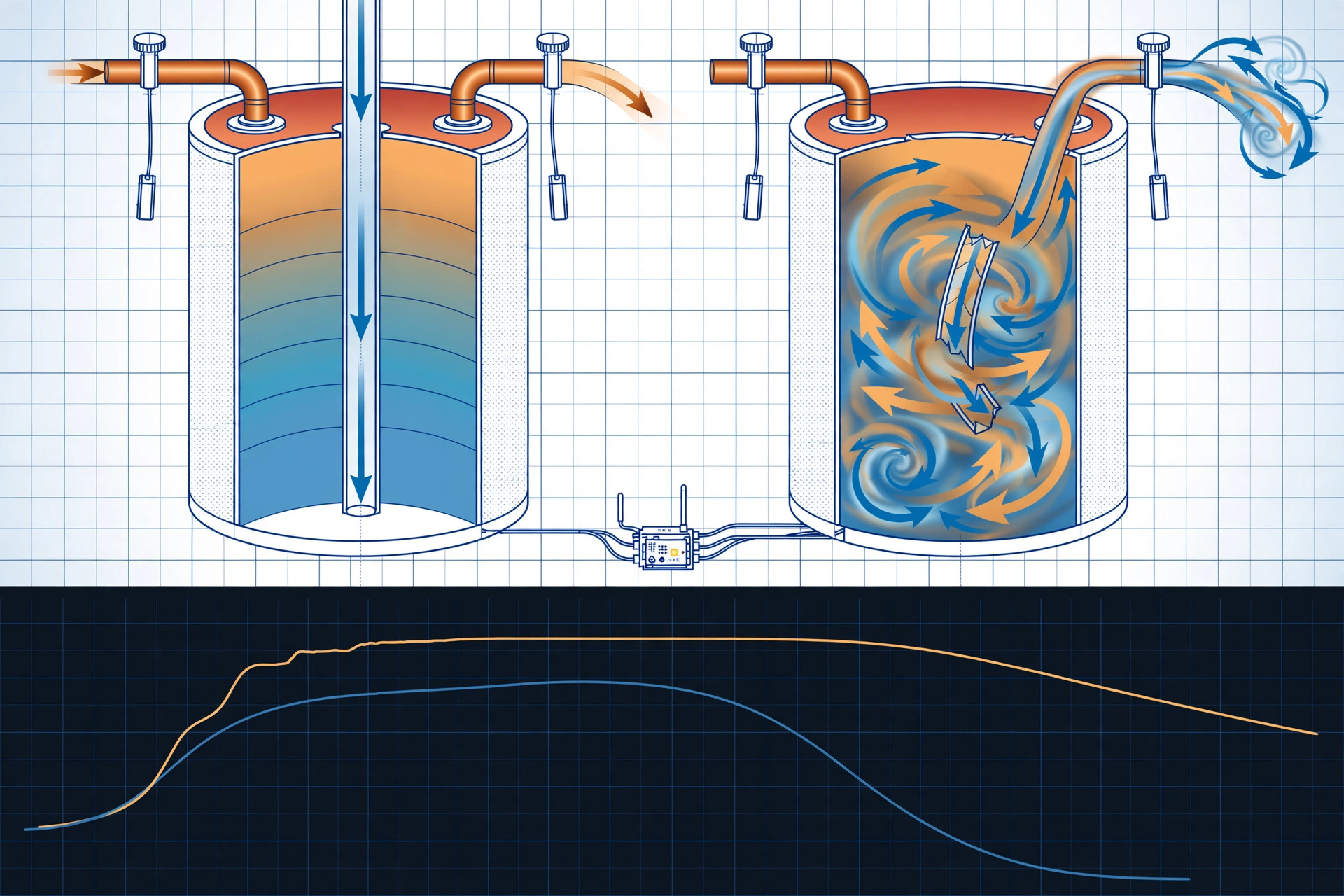
Disclosed is a system and method for diagnosing dip tube failure in storage-type water heaters without opening the plumbing. Strap-on temperature sensors on the hot outlet and cold inlet pipes, combined with a hot-water flow signal, feed an edge-deployed inference module that analyzes the tank's thermal drawdown curve during each draw event. A healthy tank holds outlet temperature near setpoint until the rising thermocline reaches the outlet; a failed dip tube lets cold inlet water discharge near the top of the tank and short-circuit to the outlet, collapsing outlet temperature within seconds of flow onset. The system learns a household-specific baseline drawdown fingerprint, compensates for seasonal inlet temperature drift, and distinguishes dip tube failure from failed heating elements, failed thermostats, undersized tanks, thermostatic mixing valve faults, and fixture cross-connections. On confirmed diagnosis it issues a tiered advisory naming the failed part and the corrective action.
Technical Field
This disclosure relates to residential water heater diagnostics, specifically to non-invasive detection of dip tube failure through thermal-fluid transient analysis and edge-deployed classification. It sits at the intersection of plumbing prognostics and embedded sensing: repurposing strap-on temperature measurements and flow data as a diagnostic instrument for an internal component that is otherwise inspectable only by disassembling the cold water inlet connection.
Background
In a storage water heater, the dip tube is a plastic tube that carries incoming cold water from the top inlet connection down to near the tank bottom. Hot water is drawn from a separate outlet at the top. This arrangement maintains thermal stratification: a hot layer floats on top of a colder layer, separated by a relatively sharp transition zone called the thermocline. During a draw, the thermocline rises as cold water enters at the bottom; outlet temperature stays near the thermostat setpoint until the thermocline reaches the outlet, then falls steeply. A healthy residential tank typically delivers 70 to 80 percent of its rated volume as usable hot water before outlet temperature drops materially, which is the physical basis of the industry's first-hour rating.
Dip tubes fail. They crack from water hammer fatigue, break off at the inlet nipple from installation stress, or chemically degrade. The most documented episode involved polypropylene dip tubes manufactured by Apcom Inc. and Perfection Corp. between 1993 and 1997, which deteriorated prematurely inside water heaters; more than twenty consumer class actions filed in July 1999 led to a nationwide settlement under which six major tank manufacturers replaced tubes at no cost (Plumbing & Mechanical, 2000; Perfection Corp. v. Lochinvar Corp.). Reported symptoms were loss of hot water pressure and temperature and white plastic particles appearing at faucet aerators. Failures continue today from mechanical causes: a plumber forum thread from 2010 documents a service call where strips of failing dip tube were found clogging a faucet supply line in a water heater installed in the early 1990s, fifteen years after the defective product was classified as such.
When the dip tube fails, cold inlet water discharges near the top of the tank, directly adjacent to the hot outlet. Cold water short-circuits to the outlet instead of sinking to the bottom. The household symptom is lukewarm water and showers that "run out of hot water" far sooner than the tank's rating suggests, sometimes within minutes.
The standard diagnosis today is invasive and frequently wrong. A technician shuts off the water, disconnects the cold inlet piping, and pulls the dip tube for visual inspection, a service call costing roughly $150 to $300 before any repair. More commonly, no inspection happens at all: because the symptom (insufficient hot water) is identical to that of a failed lower heating element or a failed thermostat, technicians routinely replace elements or thermostats first. The homeowner pays for parts and labor that cannot fix the problem, the real fault persists, and the eventual correct diagnosis requires a second visit. No non-invasive diagnostic method for dip tube condition is in common use; tank monitoring products track temperature, leak detection, or anode condition, but none infer the state of the dip tube from thermal drawdown behavior.
The gap in the art is a diagnostic that: (a) requires no plumbing disassembly or tank intrusion, (b) distinguishes dip tube failure from the electrically similar failure modes that cause the same household complaint, (c) adapts to each household's tank size, setpoint, and seasonal inlet temperature rather than applying a fixed threshold, and (d) tracks progressive degradation so the failure is caught while the tube is cracking rather than after it has fully broken off.
Detailed Description
1. Sensor Hardware
Two strap-on temperature sensor pucks clamp to the exterior of the hot outlet pipe and the cold inlet pipe within 30 cm of the tank connections. Each puck contains a platinum RTD or calibrated thermistor, a spring-loaded thermal pad, and an insulating shroud that isolates the sensing element from ambient air. Pipe-wall temperature tracks water temperature inside with a lag of seconds on copper pipe; the system characterizes this lag during commissioning and deconvolves it in software. Target per-puck cost at volume: under $8.
Flow information arrives through one of three paths, in decreasing order of preference: (a) a clamp-on ultrasonic transit-time flow meter on the hot outlet pipe, (b) a whole-house smart water meter API (e.g., Flume) with hot-draw disambiguation from the temperature channels, or (c) flow inferred from the cold inlet pipe's temperature transient, since the onset of flow produces a sharp, detectable cooling of the inlet pipe wall as stagnant warm water is displaced. Path (c) requires no flow hardware at all and is the preferred low-cost embodiment; its flow-rate estimates are coarse (±25%) but sufficient for the normalized features the classifier uses.
An optional third temperature puck straps to the tank wall at mid-height to observe thermocline passage directly. All pucks report to an edge compute node (ESP32-class microcontroller with BLE/Wi-Fi) that timestamps, filters, and stores the time series locally. Raw temperature data never leaves the premises in the default configuration.
2. Draw Event Detection and Segmentation
The edge node continuously monitors the hot outlet temperature and the flow signal. A draw event begins when flow exceeds a threshold (default 0.5 gpm) or, in the no-flow-meter embodiment, when the inlet pipe temperature drops faster than 0.5 °C per 10 seconds while the outlet temperature is above 40 °C. The event ends when flow ceases for more than 60 seconds. Each event is stored as a draw record: outlet temperature series T_out(t), inlet temperature series T_in(t), flow series Q(t), event duration, and total volume drawn.
Draws shorter than 30 seconds or smaller than 1 gallon are discarded as noise (hand washing, toilet refills on mixed lines). Overnight standby periods with zero flow are used to estimate the tank's heat loss rate and the pipe-wall thermal lag, which calibrate the deconvolution applied to draw records.
3. Thermal Drawdown Model of a Healthy Tank
For a tank of volume V with an intact dip tube, outlet temperature during a draw at flow rate Q follows the stratified-depletion model: T_out(t) remains within a few degrees of the setpoint T_set until the cumulative drawn volume approaches the usable hot water fraction, then drops steeply as the thermocline passes the outlet. Thermocline arrival time t_tc ≈ f·V/Q, where f is the usable fraction (typically 0.70 to 0.80 for a healthy residential tank). The drop is sharp because the thermocline is thin relative to tank height when the dip tube delivers cold water to the bottom without jet-induced mixing.
The system fits this model to each household's draws during a two-week commissioning period, estimating f, T_set, and the household's characteristic draw flow rates. These fitted parameters form the baseline fingerprint. Seasonal drift in inlet temperature T_in (which can swing 15 °C or more between winter and summer in cold climates) shifts the post-thermocline floor of the curve but not the normalized time-to-drop; the model normalizes time by cumulative volume drawn, keeping the fingerprint insensitive to inlet temperature.
4. Dip Tube Failure Signature
A failed dip tube changes the flow path: cold water enters near the top of the tank and mixes directly into the hot layer feeding the outlet. The drawdown signature differs from the healthy model in four measurable ways:
- Early collapse: outlet temperature begins falling within seconds of flow onset rather than holding near setpoint. Normalized time-to-10°F-drop falls below 0.25 of the baseline fingerprint value (healthy: 0.70 to 0.80).
- Flow-correlated decay: the rate of outlet temperature decline dT_out/dt tracks the instantaneous flow rate Q(t); pausing the draw pauses the decline. In a healthy tank, pausing flow after thermocline arrival does not restore outlet temperature, because the thermocline position is set by cumulative volume.
- Small inlet-outlet differential: during the draw, T_out converges toward T_in much faster than the healthy model predicts, since the outlet is increasingly fed by short-circuited inlet water rather than by the stored hot layer.
- Normal inter-draw recovery: between draws, the heating elements reheat the tank and stratification re-establishes, so the first minute of the next draw reads near setpoint before collapsing again. This "recovers, then collapses" pattern is the signature's most discriminating feature against element failure.
Partial failures (a cracked tube that still delivers most water to the bottom, or a tube broken halfway down) produce intermediate signatures: the collapse begins later than a fully broken tube but earlier than the healthy baseline. The classifier outputs a continuous degradation score from 0 (healthy) to 1 (fully failed), enabling trend tracking.
5. Differential Diagnosis Classifier
An on-device classifier (gradient-boosted decision trees, model size under 200 KB, inference under 50 ms per draw record) assigns each draw to one of six conditions using features extracted from the draw record and the household baseline:
- Healthy: drawdown matches the baseline fingerprint within tolerance.
- Dip tube failure: early collapse, flow-correlated decay, small inlet-outlet differential, normal inter-draw recovery. Degradation score above 0.6 on three consecutive qualifying draws.
- Failed lower heating element (electric tanks): normal drawdown shape on the first draw of the day but progressively shorter usable fractions across successive draws, with slow or absent temperature recovery between draws. The collapse is thermocline-driven (late, sharp), not flow-onset-driven (early, gradual).
- Failed thermostat or upper element: outlet temperature never reaches the historical setpoint even after long standby; recovery between draws is absent or partial. Distinguished from dip tube failure by the missing inter-draw recovery.
- Undersized or normally depleted tank: healthy-shaped curve with a short usable fraction that is stable across weeks (no progressive drift) and consistent across all draw sizes. The fingerprint was simply never long.
- Thermostatic mixing valve fault or fixture cross-connection: outlet temperature oscillation or step changes uncorrelated with cumulative volume, or cold intrusion correlated with a specific fixture's usage pattern rather than with every draw.
The classifier is trained on synthetic draw records generated from a lumped-parameter tank simulator spanning tank sizes (30 to 120 gallons), fuel types (electric, gas), setpoints, inlet temperatures, flow rates, and failure modes with graded severity, then fine-tuned on field data. Because the features are normalized by each household's own baseline, the model transfers across installations without per-site labeling.
6. Baseline Learning and Drift Detection
After commissioning, the system updates the baseline fingerprint with an exponentially weighted moving average over healthy-classified draws (time constant: 30 days), so gradual legitimate changes such as thermostat setpoint adjustments or seasonal inlet shifts do not trigger false alarms. A separate long-term trend tracker monitors the degradation score; a monotonic rise over four or more weeks, even while individual draws still classify as healthy, generates a "watch" advisory for progressive tube cracking. Sudden step changes in the score (e.g., after a water hammer event) are flagged as acute failures and correlated with any available pressure transient data.
7. Advisory Outputs
Advisories are tiered. Watch: degradation score trending upward; no action required; recheck in 30 days. Schedule service: dip tube failure confirmed on three consecutive qualifying draws; advisory names the part (dip tube, with the tank manufacturer and model number pulled from a user-entered or photographed rating plate), the expected repair (drain-down, inlet nipple removal, tube replacement; approximately 1 to 2 hours labor), and the consequence of delay (continued lukewarm water, plastic particle migration into aerators and appliance inlet screens). Urgent: degradation score above 0.9 combined with evidence of particle migration (inferred from repeated short-cycle flow anomalies at fixtures); recommends prompt replacement before particles damage washing machine or dishwasher inlet valves.
Each advisory includes a plumber-facing report: the drawdown curves for the three confirming draws overlaid on the household baseline, the degradation score trend, and the differential diagnosis table showing why element, thermostat, and mixing valve faults were ruled out. This report is designed to prevent the common misdiagnosis cascade in which a failed dip tube is treated as a failed element.
8. Figures Description
- Figure 1: Cutaway schematic of a storage water heater with an intact dip tube, showing cold water delivery to the tank bottom, thermal stratification layers, thermocline position, and strap-on sensor puck locations on the hot outlet and cold inlet pipes.
- Figure 2: Cutaway schematic of the same tank with a broken dip tube, showing cold water discharging near the top and short-circuit flow paths to the hot outlet.
- Figure 3: Overlaid outlet temperature versus cumulative volume curves for a healthy draw (sustained plateau, late steep drop at thermocline arrival) and a dip-tube-failure draw (early flow-correlated collapse), with the household baseline fingerprint band shaded.
- Figure 4: Inter-draw recovery comparison: outlet temperature at draw start across five consecutive draws for dip tube failure (recovers to setpoint between draws, collapses during each draw) versus failed lower element (declining start temperatures, no recovery).
- Figure 5: System block diagram: sensor pucks, flow signal paths, edge compute node, baseline learning module, differential diagnosis classifier, and advisory outputs.
Claims
- A system for diagnosing dip tube failure in a storage water heater, comprising: a first temperature sensor configured for non-invasive strap-on mounting to the hot water outlet pipe; a second temperature sensor configured for non-invasive strap-on mounting to the cold water inlet pipe; a flow signal source indicating hot water draw flow rate; and an edge-deployed inference module that records outlet temperature, inlet temperature, and flow during draw events, computes a thermal drawdown curve for each draw, and classifies dip tube condition by comparing the drawdown curve against a household-specific baseline fingerprint.
- The system of claim 1, wherein the inference module detects dip tube failure from an early-collapse signature comprising outlet temperature decline beginning within the first quarter of the baseline usable-fraction volume, a rate of decline correlated with instantaneous flow rate, and convergence of outlet temperature toward inlet temperature faster than the baseline fingerprint predicts.
- The system of claim 1, wherein the inference module distinguishes dip tube failure from heating element or thermostat failure using inter-draw recovery behavior: dip tube failure exhibits outlet temperature recovery to near setpoint between draws followed by collapse during each draw, while element or thermostat failure exhibits absent or declining inter-draw recovery.
- The system of claim 1, wherein the household-specific baseline fingerprint is learned during a commissioning period by fitting a stratified-depletion thermocline model to observed draws, and is thereafter updated with an exponentially weighted moving average over healthy-classified draws to absorb seasonal inlet temperature drift and setpoint changes.
- The system of claim 1, wherein the flow signal source is the cold inlet pipe temperature transient itself, with draw onset detected from the rate of inlet pipe wall cooling as stagnant water is displaced, requiring no dedicated flow meter hardware.
- The system of claim 1, wherein the inference module outputs a continuous degradation score from healthy to fully failed, and a long-term trend tracker generates a watch advisory on monotonic score increase over multiple weeks before any individual draw classifies as failed.
- The system of claim 1, further comprising a differential diagnosis classifier that assigns each draw among healthy, dip tube failure, failed heating element, failed thermostat, undersized tank, and mixing valve or cross-connection fault using features normalized by cumulative volume drawn.
- The system of claim 1, further comprising an advisory module that, on confirmed dip tube failure across multiple consecutive qualifying draws, generates a report comprising overlaid drawdown curves against the baseline fingerprint, the degradation score trend, the differential diagnosis rationale, the replacement part identification, and the expected repair procedure.
- A method for non-invasive diagnosis of water heater dip tube failure, comprising: strap-mounting temperature sensors to the exterior of the hot outlet and cold inlet pipes without modifying the plumbing; recording outlet temperature, inlet temperature, and a flow signal across a plurality of hot water draw events; fitting a stratified-depletion baseline model to the recorded draws; detecting a flow-correlated early collapse of outlet temperature relative to the baseline; verifying normal inter-draw temperature recovery to rule out heating element and thermostat faults; and issuing a dip tube replacement advisory upon confirmation.
- The method of claim 9, further comprising correlating an acute step change in dip tube condition with a water hammer pressure transient to identify mechanically induced tube fracture events.
Prior Art References
- Plumbing & Mechanical, "Consumer Dip Tube Notification" (2000): National settlement over Apcom/Perfection dip tubes manufactured 1993-1997; documents symptoms (loss of hot water pressure and temperature, white particles) and the six participating tank manufacturers.
- Perfection Corp. v. Lochinvar Corp., Ill. App. Ct. (2004): Litigation record documenting premature deterioration of Prolene dip tubes, 20+ consumer class actions filed July 1999, and nationwide settlement with the tank manufacturers.
- Supply House Times, "Settlement approved in dip tube suit": Dip tubes breaking into small white pieces clogging faucets, showerheads, and appliances; affected brands including Rheem, A.O. Smith, Bradford White, American Water Heater, and Lochinvar.
- U.S. DOE Energy Saver: Water Heating: Overview of storage water heater operation, tank sizing, and efficiency; background on residential water heating systems.
- Flume Smart Home Water Monitor: Whole-house smart water meter providing flow data usable as the flow signal source for draw event segmentation.
- ESP32-S3 SoC: Espressif microcontroller with vector DSP extensions; edge compute platform for the inference module.
- TensorFlow Lite for Microcontrollers: On-device ML runtime suitable for the draw classification model.
- LITF-PA-2026-157, "System and Method for Predictive Residential Water Heater Tank Failure and Sacrificial Anode Rod Depletion Monitoring Using Galvanic Current Sensing, Water Conductivity Compensation, and Vibro-Acoustic Tank Wall Resonance Shift Analysis with On-Device Prognostic Modeling": monitors tank wall and anode condition; does not analyze thermal drawdown curves or diagnose dip tube failure.
- LITF-PA-2026-057, "System and Method for Continuous Potable Water Quality Monitoring Using Domestic Water Heater Sacrificial Anode Galvanic Current Measurement and Electrochemical Impedance Spectroscopy for Detection of Source Water Chemistry Changes and Lead Service Line Corrosion Events": uses the water heater as a water chemistry sensor; does not diagnose internal mechanical components.
- LITF-PA-2026-201, "System and Method for Quantifying Sediment Accumulation in Residential Storage Water Heaters Using Passive Smartphone Acoustic Analysis": quantifies sediment via acoustic analysis; does not measure drawdown dynamics or infer dip tube state.
- LITF-PA-2026-094, "System and Method for Continuous Residential Plumbing Integrity Assessment Using Water Hammer Transient Analysis from Smart Water Meter High-Frequency Pressure Data": analyzes pressure transients for pipe integrity; does not diagnose water heater internal components.
Implementation Notes
A minimal viable prototype can be assembled from off-the-shelf parts: two strap-on RTD pucks (PT1000 elements with spring thermal pads and foam insulating shrouds), an ESP32-S3 development board, and a clamp-on ultrasonic flow meter or a Flume-style smart meter for the flow channel, for under $120 in single-unit quantities (under $45 estimated at volume without the ultrasonic meter, using inlet-transient flow inference instead).
Bring-up procedure: strap the pucks to the hot outlet and cold inlet copper pipes within 30 cm of the tank, insulate over the shrouds, and let the system observe for two weeks covering at least ten qualifying draws. Verify the baseline fingerprint first: run a controlled draw (e.g., a bathtub fill at a measured flow rate) and confirm the fitted usable fraction lands between 0.65 and 0.85 and thermocline arrival matches cumulative volume. Then simulate a failure signature by partially closing the cold inlet valve during a draw to confirm the classifier's early-collapse detection triggers (this mimics restricted bottom delivery, not a true tube break, but exercises the same code path). Pipe-wall thermal lag on 3/4-inch copper is 5 to 15 seconds; the deconvolution filter is tuned per installation during the first three observed draws.
Expected performance envelope (design targets for a production validation program, not measured results): dip tube failure detection sensitivity target ≥90% with ≤2 false alarms per year per household; confirmation latency of three qualifying draws (typically 1 to 3 days in an occupied home); degradation score repeatability within ±0.1 across draws at fixed severity; flow inference from inlet transients accurate within ±25% on copper pipe. PEX piping increases thermal lag and attenuates the inlet transient; the no-flow-meter embodiment is validated for copper only, with the ultrasonic meter recommended for PEX installations.
Limitations: the method diagnoses the hydraulic consequence of dip tube failure (cold water short-circuiting to the outlet), not the tube's physical state directly; a tube that is cracked but still seated can produce a borderline score that requires trend confirmation over weeks. Households with continuously recirculating hot water loops will show flattened drawdown curves that mask the signature; the system detects recirculation from the persistent outlet pipe warmth during zero-flow periods and disables drawdown classification, reporting recirculation-loop incompatibility instead. Point-of-use tankless heaters have no dip tube and no storage drawdown curve; the system identifies them from the absence of any thermocline-shaped draw and declines to classify.