System and Method for Continuous Residential Electrical Grounding Integrity Monitoring Using Distributed Smart Outlet Neutral-to-Ground Voltage Spectral Analysis with Fault Localization and Progressive Corrosion Detection
Abstract
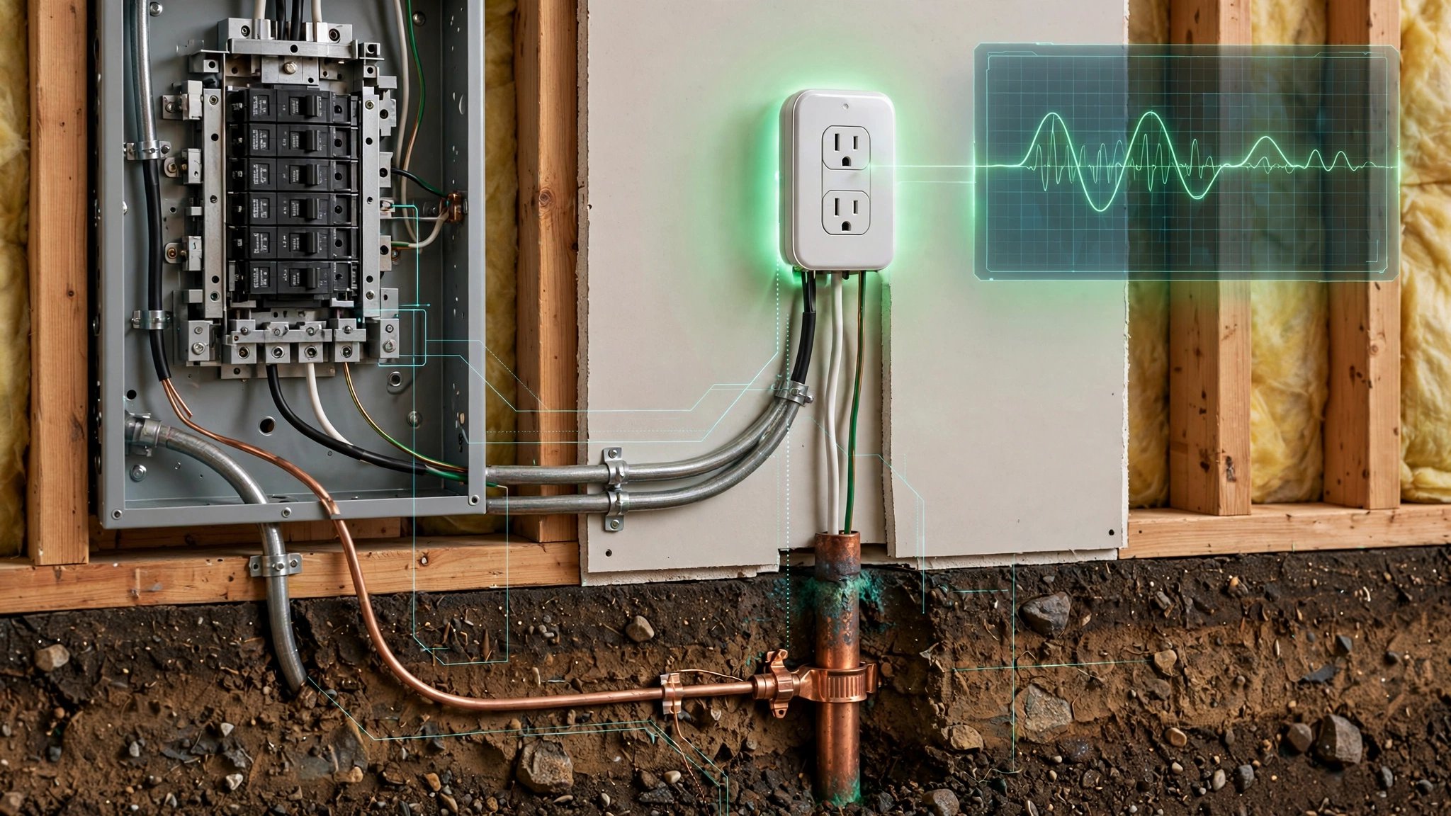
Disclosed is a system and method for continuous monitoring of residential electrical grounding system integrity using distributed smart outlets equipped with voltage measurement capability. Each participating smart outlet periodically measures the root-mean-square (RMS) voltage between the neutral and equipment grounding conductors (N-G voltage) and performs spectral decomposition of this waveform to extract the fundamental 60 Hz component and its harmonics through the 15th order (900 Hz). Under normal conditions in a properly grounded NEC-compliant residential system, N-G voltage is below 2 V RMS and exhibits a clean 60 Hz waveform dominated by the fundamental. Degraded grounding connections introduce nonlinear contact resistance at corroded junctions, generating characteristic harmonic signatures that differ by fault type: oxide-film corrosion at screw terminals produces elevated odd harmonics (3rd, 5th, 7th) due to the voltage-dependent tunneling resistance of the oxide layer; soil-moisture-driven ground rod corrosion elevates even harmonics (2nd, 4th) from the asymmetric electrochemical half-cell; and loose backstab connections produce intermittent broadband spectral energy from micro-arcing. By collecting synchronized N-G voltage spectra from multiple smart outlets across the home and applying a graph-based electrical network model, the system localizes grounding faults to specific circuit branches, tracks corrosion progression rates over weeks to months, and generates maintenance alerts before the grounding system degrades to the point of creating shock or fire hazards.
Technical Field
This invention relates to residential electrical safety monitoring, specifically to automated, continuous assessment of equipment grounding conductor integrity using voltage measurements from distributed smart outlet devices with spectral analysis for fault classification and localization.
Background
The equipment grounding conductor (EGC) is the last line of defense against electrical shock in residential buildings. When a line-to-ground fault occurs in an appliance or fixture, the EGC provides a low-impedance return path to the service panel, enabling the overcurrent protection device (breaker or fuse) to trip and clear the fault. A compromised EGC leaves metal appliance enclosures, receptacle faceplates, and plumbing fixtures energized at lethal voltage during a ground fault. The National Electrical Code (NEC) Article 250 mandates grounding electrode systems, bonding, and EGC sizing precisely because this path must have low enough impedance to trip the breaker within the fault-clearing time specified in UL 489.
Grounding system degradation is widespread and largely invisible:
- Ground rod corrosion: Copper-clad steel ground rods corrode in acidic soils (pH < 5.5) and high-chloride environments. Marungsri et al. (IEEE, 2015) measured ground rod resistance increases of 200-400% over 15 years in corrosive soils. The Copper Development Association notes that a significant fraction of aging residential ground rods exceed the NEC-recommended 25-ohm grounding electrode resistance, particularly in sandy, rocky, or low-moisture soils.
- Screw terminal corrosion: Copper-to-steel and copper-to-aluminum junctions at receptacles, switches, and panel lugs develop oxide films over time. CPSC data attributes approximately 46,000 residential electrical fires annually to faulty wiring and connections, with corroded connections being a major contributing factor.
- Backstab connection failures: Spring-tension "backstab" connections used in inexpensive receptacles are prone to loosening. The NFPA fire statistics show that electrical distribution equipment (including receptacles) is the third leading cause of home structure fires.
- Bootleg grounds: IAEI (International Association of Electrical Inspectors) documents the practice of connecting neutral to ground at individual receptacles to fool three-light testers, creating a shock hazard by energizing the EGC during normal circuit operation.
Current methods for detecting grounding problems are episodic and manual:
- Three-light receptacle testers: Cost $5-$15. Can detect open grounds, open neutrals, and reversed polarity. Cannot detect bootleg grounds, high-impedance connections, or degraded ground rods. ECM Magazine has documented how bootleg grounds fool these testers into showing "correct wiring."
- Ground impedance testing: Requires a dedicated ground impedance tester ($200-$2,000) and a qualified electrician. Measures EGC impedance from each outlet back to the panel. Rarely performed outside of new construction inspections or troubleshooting.
- Ground rod resistance testing (fall-of-potential method): Requires driving auxiliary test stakes and measuring resistance using a clamp-on ground tester or Wenner method instrument. Cost: $150-$500 per test by a qualified technician. Performed at initial installation and almost never re-tested.
The gap in the art is a system that: (a) continuously monitors grounding system health using hardware already deployed in millions of homes; (b) classifies the type of grounding degradation from electrical signatures without requiring physical access to connections; (c) localizes faults to specific circuit branches using coordinated measurements from multiple outlets; and (d) tracks degradation progression over time to enable preventive maintenance before safety thresholds are crossed.
Detailed Description
1. Neutral-to-Ground Voltage as a Grounding Health Indicator
In a residential 120/240V split-phase electrical system, the neutral conductor is bonded to the grounding electrode system at the main service panel (NEC 250.24(A)(1)). At this bonding point, neutral and ground are at the same potential. At any downstream receptacle, the N-G voltage equals the voltage drop along the neutral conductor from the outlet back to the panel, minus the voltage drop along the EGC over the same path (which is zero under normal conditions because no current flows in the EGC during fault-free operation).
Under normal loading, N-G voltage at a receptacle typically ranges from 0.5 to 2.0 V RMS, proportional to the load current on the circuit multiplied by the neutral conductor resistance (typically 0.1-0.5 ohms for 14 AWG copper over 50-100 foot runs). This voltage is a pure 60 Hz sinusoid (plus minor distortion from nonlinear loads on the same circuit) because it results from simple resistive voltage division.
When the EGC or grounding electrode system degrades, the N-G voltage changes in three diagnostically useful ways:
- Magnitude increase: A high-impedance EGC allows voltage to develop across the ground conductor during normal operation due to capacitive coupling and stray currents, raising the baseline N-G voltage.
- Waveform distortion: Corroded junctions introduce nonlinear resistance (voltage-dependent). The resulting N-G voltage waveform acquires harmonic content that is absent in the purely resistive case.
- Temporal instability: Loose connections produce intermittent contact, causing rapid fluctuations in N-G voltage magnitude and spectral content.
2. Smart Outlet Measurement Hardware
Consumer smart outlets with energy monitoring (e.g., TP-Link Kasa EP25, Shelly Plug S, Meross MSS310) already contain voltage measurement circuitry. The typical measurement chain consists of a resistive voltage divider from the hot conductor to a sigma-delta ADC (e.g., HLW8032, BL0937, or ADE7953) sampling at 3.2 kHz or higher with 16-bit resolution. This ADC architecture provides sufficient bandwidth and dynamic range to capture harmonics through the 15th order (900 Hz) with better than 60 dB signal-to-noise ratio.
The disclosed system requires a firmware modification to existing smart outlet hardware that adds one measurement channel: the voltage between the neutral and ground pins of the receptacle. In outlets using the HLW8032 metering IC, the differential voltage input (VP-VN) can be reconfigured during a calibration window to measure N-G voltage instead of the hot-neutral voltage used for power metering. Alternatively, a dedicated resistive divider from neutral to ground (100 kΩ / 1 kΩ, dissipating < 150 µW) can feed a GPIO ADC input on the microcontroller (typically ESP8266 or ESP32) at 12-bit resolution and 1 kHz sample rate. The measurement is non-invasive, draws negligible current through the grounding conductor, and does not compromise the safety function of the EGC.
Each outlet acquires 1-second N-G voltage waveform snapshots at configurable intervals (default: every 5 minutes). Each snapshot comprises 1,000 samples at 1 kHz, sufficient for spectral analysis through 500 Hz (8th harmonic of 60 Hz, with the 15th harmonic accessible via the metering IC's higher sample rate).
3. Spectral Decomposition and Fault Signature Classification
Each 1-second N-G voltage waveform is processed on-device using a 1024-point FFT with Hann windowing. The output is a magnitude spectrum with approximately 1 Hz frequency resolution. The system extracts the following feature vector from each measurement:
- Fundamental magnitude (60 Hz), V RMS
- Total harmonic distortion (THD) of the N-G voltage, percent
- Individual harmonic magnitudes: 2nd (120 Hz) through 15th (900 Hz)
- Odd-to-even harmonic ratio (OER)
- Spectral centroid of the harmonic content
- Inter-measurement variance (computed over the last 12 readings, 1 hour at default interval)
- Crest factor of the N-G voltage waveform
Fault type classification uses a random forest model (50 trees, max depth 8) trained on labeled data from controlled laboratory fault simulations. The fault taxonomy comprises five classes:
- Normal: N-G RMS < 2.0 V, THD < 5%, low variance. Healthy grounding system with typical neutral loading.
- Oxide-film corrosion (screw terminal): N-G RMS 2-8 V, THD 10-25%, OER > 3.0 (strong odd harmonics). The voltage-dependent tunneling resistance of copper oxide (Cu₂O) and tin oxide (SnO₂) films produces a symmetric nonlinearity that generates predominantly odd-order harmonics, analogous to the harmonic generation in a soft-clipping amplifier.
- Electrochemical corrosion (ground rod): N-G RMS 3-15 V, THD 8-20%, OER < 1.5 (elevated even harmonics). The asymmetric half-cell at the corroded ground rod/soil interface produces a DC bias in the grounding impedance that generates even-order harmonics when AC currents flow through it, similar to the behavior of a corroded diode junction. (This signature is predicted from electrochemical impedance theory; laboratory validation with controlled soil conditions and accelerated corrosion protocols is recommended to calibrate the classifier thresholds for field deployment.)
- Loose/intermittent connection (backstab): High inter-measurement variance (> 30% coefficient of variation in N-G RMS over 1 hour), broadband spectral energy from micro-arcing during contact bounce, elevated crest factor (> 2.0) from transient voltage spikes.
- Bootleg ground (neutral-to-ground bond at outlet): Anomalously low N-G voltage (< 0.1 V RMS) at a single outlet when other outlets on the same circuit show normal N-G voltage. The bootleg bond forces N-G voltage to zero locally but does not reduce it elsewhere, creating a distinctive spatial pattern.
4. Distributed Fault Localization via Graph-Based Network Modeling
When multiple smart outlets are deployed across a home (3-8 outlets is the typical consumer installation), the system constructs an electrical network graph where nodes represent measurement points (outlets) and edges represent wiring segments between them. The graph topology is inferred during an initial learning phase by correlating N-G voltage waveforms across outlets: outlets on the same circuit exhibit highly correlated N-G voltage fluctuations (Pearson r > 0.9) because they share the same neutral conductor return path.
Fault localization proceeds by analyzing the spatial pattern of N-G voltage anomalies across the network:
- Panel-side fault (main bonding jumper, grounding electrode conductor, ground rod): All outlets show elevated N-G voltage and similar harmonic signatures. The fault is upstream of the entire distribution system.
- Branch circuit fault (circuit-level EGC): Outlets on one circuit show elevated N-G voltage while outlets on other circuits remain normal. The fault is on the EGC of the affected branch circuit, between the panel and the first affected outlet.
- Outlet-local fault (single receptacle): One outlet shows anomalous N-G voltage while adjacent outlets on the same circuit do not. The fault is at the specific receptacle's ground connection.
- Downstream fault: Using the serial topology of outlets on a circuit (daisy-chained wiring), faults between two adjacent measurement points can be isolated to the wiring segment between them by comparing their N-G voltage magnitudes. The outlet downstream of the fault will show a larger N-G voltage increase than the upstream outlet.
The graph model uses a minimum spanning tree algorithm weighted by measured inter-outlet N-G voltage correlation to infer circuit topology, then applies Kirchhoff's voltage law constraints to solve for the location and impedance magnitude of the fault within the network.
5. Temporal Tracking and Predictive Maintenance
The system stores daily summary statistics (mean N-G RMS, mean THD, harmonic feature vector, fault classification confidence) for each outlet. A linear regression model applied to the 90-day history of each feature detects progressive degradation trends. Alert thresholds are calibrated to NEC-relevant safety limits:
- Advisory (yellow): N-G RMS exceeds 3.0 V or THD exceeds 10%. Grounding impedance is elevated but the EGC is likely still functional for fault clearing. Recommend professional inspection within 30 days.
- Warning (orange): N-G RMS exceeds 5.0 V, or inter-measurement variance exceeds 40% (indicating intermittent connection), or trend projection shows N-G RMS crossing 5.0 V within 30 days. EGC impedance may be too high to clear faults within the required time. Recommend professional inspection within 7 days.
- Critical (red): N-G RMS exceeds 10.0 V, or micro-arcing spectral signature detected (broadband energy above 300 Hz with crest factor > 3.0), or bootleg ground detected. Immediate fire or shock hazard. Recommend de-energizing the affected circuit and emergency electrician response.
The predictive model accounts for environmental factors by correlating N-G voltage trends with temperature and humidity data (from co-located smart home sensors or regional weather APIs). Soil moisture affects ground rod resistance seasonally, and thermal cycling accelerates oxide film growth at screw terminals. By modeling these environmental correlations, the system distinguishes between reversible seasonal fluctuations and irreversible corrosion progression.
6. Calibration and Self-Test
Each outlet performs a daily self-test by verifying that its N-G voltage measurement chain produces a reading within 10% of the expected value calculated from the hot-neutral voltage, the known load on the circuit (measured by the outlet's power monitoring), and the estimated neutral conductor impedance (derived from historical N-G/load current regression). If the self-test fails, the outlet flags its own measurement as unreliable and requests cross-validation from neighboring outlets on the same circuit.
Initial calibration occurs during installation when the homeowner performs a brief enrollment sequence: turning on and off a known load (e.g., a 100W incandescent lamp) at each monitored outlet. The resulting step change in N-G voltage, combined with the known load current, provides a direct measurement of the neutral conductor impedance to that outlet, establishing the baseline for subsequent anomaly detection.
7. Implementation Notes
The firmware modification requires approximately 8 KB of additional flash memory for the FFT library, feature extraction, and random forest classifier. RAM requirements are 4 KB for the 1024-point FFT buffer and feature vector. These resources are well within the capabilities of ESP8266 (1 MB flash, 80 KB RAM) and ESP32 (4 MB flash, 520 KB RAM) microcontrollers used in commercial smart outlets.
Data transmission to the cloud aggregation service adds approximately 200 bytes per measurement (feature vector + metadata), or 58 KB per day at the default 5-minute interval. This is negligible compared to the existing telemetry bandwidth of smart outlets (which typically report power measurements at 1-second intervals).
The system requires no additional hardware beyond the firmware update. The only physical requirement is that the outlet be installed in a properly wired three-prong receptacle with hot, neutral, and ground conductors present. In two-prong (ungrounded) receptacles, the system detects the absence of a ground conductor and reports the outlet as ungrounded rather than attempting grounding diagnostics.
The principles disclosed herein apply equally to 50 Hz electrical systems (Europe, Asia, most of the world outside North America), with appropriate adjustment of the fundamental frequency and harmonic bin indices. The approach extends to three-phase commercial and industrial installations by monitoring phase-to-ground voltages at distributed measurement points. Communication between outlets may use any wireless protocol (WiFi, Zigbee, Z-Wave, Matter/Thread, Bluetooth Mesh) or wired protocols (powerline communication) without changing the core measurement and analysis methodology.
8. Figures Description
- Figure 1: System architecture showing distributed smart outlets connected via WiFi to a cloud aggregation service, with the electrical network graph overlay illustrating circuit topology inference from N-G voltage correlations.
- Figure 2: N-G voltage waveforms and corresponding FFT magnitude spectra for each of the five fault classes: normal, oxide-film corrosion (odd harmonics dominant), electrochemical ground rod corrosion (even harmonics elevated), loose backstab connection (broadband spectral energy), and bootleg ground (near-zero N-G voltage).
- Figure 3: Temporal trend plot showing 90-day progression of N-G RMS voltage and THD at a single outlet as a screw terminal corrosion develops, with advisory/warning/critical thresholds marked and the predictive regression line indicating estimated time to warning threshold.
- Figure 4: Distributed fault localization example in a 6-outlet deployment, showing the graph-based network model identifying a branch circuit EGC fault between outlets 3 and 4 based on the spatial pattern of N-G voltage anomalies.
Claims
- A system for continuous monitoring of residential electrical grounding integrity, comprising: a plurality of smart outlet devices, each containing a voltage measurement circuit capable of measuring the voltage between the neutral conductor and the equipment grounding conductor; a spectral analysis module that performs frequency-domain decomposition of the measured neutral-to-ground voltage waveform to extract harmonic magnitudes through at least the 7th harmonic order; and a fault classification module that identifies the type of grounding degradation based on the relative magnitudes of odd-order and even-order harmonics, inter-measurement temporal variance, and waveform crest factor.
- The system of claim 1, wherein oxide-film corrosion at screw terminals is identified by an odd-to-even harmonic ratio exceeding 3.0 in the neutral-to-ground voltage spectrum, reflecting the symmetric nonlinear resistance characteristic of metal oxide tunnel junctions.
- The system of claim 1, wherein electrochemical corrosion of a grounding electrode is identified by elevated even-order harmonics in the neutral-to-ground voltage spectrum, reflecting the asymmetric electrochemical impedance of the corroded electrode-soil interface.
- The system of claim 1, wherein loose or intermittent grounding connections are identified by a coefficient of variation in neutral-to-ground RMS voltage exceeding 30% over a sliding window, combined with broadband spectral energy above the 5th harmonic order indicative of micro-arcing at the contact interface.
- The system of claim 1, wherein bootleg grounding (unauthorized neutral-to-ground bond at the outlet) is identified by anomalously low neutral-to-ground voltage at a single measurement point relative to other measurement points on the same branch circuit.
- A method for localizing grounding faults in a residential electrical system, comprising: measuring neutral-to-ground voltage spectra at a plurality of smart outlet locations distributed across the electrical system; inferring branch circuit topology by computing pairwise correlation coefficients of neutral-to-ground voltage waveforms across all outlet pairs, wherein outlets sharing a branch circuit exhibit correlation coefficients exceeding a threshold; constructing a graph-based electrical network model with measurement points as nodes and wiring segments as edges; and solving for the fault location and impedance magnitude using the spatial pattern of neutral-to-ground voltage anomalies constrained by Kirchhoff's voltage law relationships in the network model.
- The method of claim 6, further comprising temporal trend analysis of daily neutral-to-ground voltage statistics over a 90-day window to detect progressive grounding degradation, with predictive alerting when linear regression projects that the neutral-to-ground voltage will exceed a safety threshold within a configurable forecast horizon.
- The method of claim 7, further comprising environmental compensation by correlating neutral-to-ground voltage trends with ambient temperature, humidity, and soil moisture data to distinguish reversible seasonal variations in grounding electrode resistance from irreversible corrosion progression.
- The system of claim 1, wherein each smart outlet performs a daily self-test by comparing its measured neutral-to-ground voltage against an expected value calculated from the hot-to-neutral voltage, measured load current, and historically calibrated neutral conductor impedance, flagging its own measurement as unreliable if the measured value deviates by more than 10% from the expected value.
- A system for grounding integrity monitoring implemented as a firmware update to existing consumer smart outlets containing voltage measurement integrated circuits, wherein the firmware modification adds neutral-to-ground voltage measurement, on-device spectral analysis, fault classification, and network-coordinated fault localization without requiring additional hardware components beyond those present in the unmodified smart outlet.
- The system of claim 1, further comprising a tiered alert system with advisory, warning, and critical thresholds calibrated to NEC-relevant safety limits, wherein advisory alerts are generated when neutral-to-ground RMS voltage exceeds 3.0 V, warning alerts when it exceeds 5.0 V or when intermittent connection signatures are detected, and critical alerts when it exceeds 10.0 V or when micro-arcing spectral signatures are present.
Prior Art References
- NFPA 70 (National Electrical Code) — Article 250: Grounding and Bonding requirements for residential electrical systems
- Marungsri et al., IEEE 2015 — Ground rod corrosion and resistance degradation in tropical soils over 15-year field study
- Copper Development Association — Practical guide to residential grounding electrode installation and soil resistivity
- CPSC Electrical Wiring Fire Data — Approximately 46,000 annual residential electrical fires attributed to faulty wiring and connections
- NFPA Fire Statistics — Electrical distribution equipment as third leading cause of home structure fires
- IAEI Magazine — Bootleg grounds: detection challenges and shock hazard documentation
- ECM Magazine — Limitations of three-light testers for detecting bootleg grounds
- UL 489 — Molded-case circuit breaker fault-clearing time requirements
- Braunovic et al., IEEE Holm Conference 2003 — Contact resistance behavior of corroded copper and aluminum connections under AC loading
- Espressif ESP32 SoC — Dual-core microcontroller with 12-bit ADC, 520 KB SRAM, WiFi, used in commercial smart outlets
- IEEE Std 142-2007 (Green Book) — Recommended Practice for Grounding of Industrial and Commercial Power Systems
- NFPA Home Electrical Fire Report — Detailed breakdown of electrical fire causes, ignition sources, and contributing factors