System and Method for Predicting Septic Drain Field Hydraulic Failure Using Effluent Pump Electrical Signature Analysis and Infiltrative Surface Sentinel Fusion
Abstract
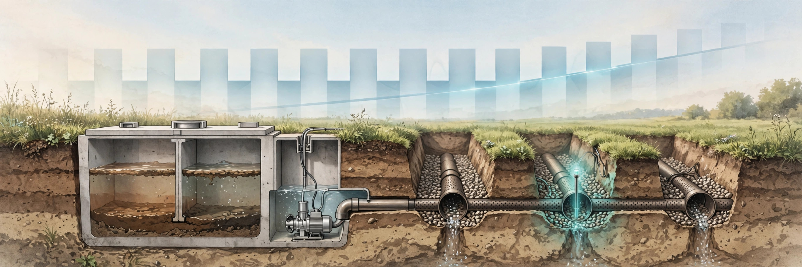
Disclosed is a system and method for predicting hydraulic failure of septic drain fields months before sewage surfaces or backs up into the home, using a non-intrusive electrical signature of the effluent dosing pump fused with buried infiltrative-surface sentinel measurements. A split-core current sensor clamped on the effluent pump branch circuit, requiring no plumbing or wiring changes, samples pump motor current and extracts each dose cycle's run time, inter-dose interval, and running current from the current envelope. In demand-dosed systems the dose volume is fixed by float-switch geometry, so when ponding develops in the trenches the excess effluent drains back between doses, the pump chamber refills faster, and the inter-dose interval shortens while dose run time stays constant: cycles per day rise at constant household water use. This invariant, the dose-frequency-to-usage ratio, drifts upward as the biomat clogs and soil hydraulic conductivity falls, providing the primary early warning. Buried sentinel probes at infiltrative-surface depth in a representative trench measure volumetric water content and soil temperature, confirming the electrical signal: moisture that fails to fall below field capacity between doses indicates impaired drainage, and damped diurnal temperature amplitude indicates saturation, because water carries far more heat per unit volume than dry soil. A Field Health Index fuses the electrical and sentinel features through exponentially weighted moving averages, and a differential-diagnosis engine separates six fault modes: drain-field hydraulic failure, effluent pump wear, float-switch failure, clogged effluent filter, excessive household loading, and seasonal high-water-table saturation. Escalating alerts recommend field resting, lateral alternation, effluent-screen cleaning, or professional inspection, catching the most expensive septic failure, a drain field replacement costing $5,000 to $20,000, months before sewage backs up into the home.
Field of the Invention
This invention relates to onsite wastewater treatment systems, specifically to predictive monitoring of septic drain field hydraulic capacity through non-intrusive electrical signature analysis of the effluent dosing pump combined with buried soil moisture and temperature sensing, enabling early detection of biomat clogging and automated root-cause diagnosis of dosing anomalies.
Background
More than one-fifth of U.S. households treat their wastewater with individual onsite septic systems (EPA SepticSmart), totaling more than 21 million households (Circle of Blue). A conventional system is simple: the septic tank settles solids and digests organic matter, and clarified effluent flows or is pumped to the drain field, where a network of perforated pipes in gravel trenches distributes it over soil. At the trench-soil interface a biomat forms, a 1 cm to 5 cm band of organic material and bacteria that is essential for treatment but restricts flow (InspectAPedia). The EPA's own technology fact sheet states the failure mechanism plainly: soil absorption systems "are occasionally unable to accept the total daily wastewater load they receive, leading to ponding and eventual hydraulic failure," caused by "the accumulation of biomass and suspended solids in or near the biomat, which reduces the soil's porosity and hydraulic conductivity" (EPA SWIS fact sheet).
Once the biomat thickens past the point where the hydraulic loading rate exceeds the soil's infiltration rate, ponding starts in the trenches. From there the system has two exits, both bad: wastewater backs up into the home, or it breaks out onto the soil surface (InspectAPedia). The EPA warns that when a drain field is more than 25 to 30 years old, the thickened biomat "can cause ponding in the drainfield, surfacing of untreated wastewater, or backing up into the septic tank and into the plumbing in the house," and advises planning for an upgrade before an emergency (EPA). Without good maintenance, EPA estimates the functioning life of a septic system is typically 20 years or less (EPA technology fact sheet), while regular pumping every 3 to 5 years can extend systems to 20 to 30 years or more (EPA risk assessment guide).
Current practice detects all of this late and manually. The signs of a failed drain field are the ones a homeowner notices only when damage is done: sewage backing up into drains, wet soggy areas above the field, spongy bright-green grass, and odors near the tank or field (Washington DOH). A professional inspection then means opening tanks, checking sludge levels, and possibly excavating parts of the drain field to look for ponding, or checking observation ports for standing water (EPA). Island County, Washington's deficiency guide confirms the diagnostic: "If large amounts of ponding wastewater are seen in your drainfield observation ports, this may indicate that the soil helping treat and disperse the wastewater is oversaturated," and repeated ponding means the soil "is no longer useful and drainfield repair or replacement are necessary" (Island County). Notably, the EPA's recommended first step when a system fails hydraulically is to "pump the septic tank and clean and replace the effluent screen," not to replace the field (EPA SWIS fact sheet), which means many fields are condemned that could have been saved by early intervention. Existing electronic monitors are limited to high-water alarm floats that only trigger when failure is already in progress.
The economics make early detection valuable. Drain field replacement costs $5,000 to $20,000 in the typical range, averaging $7,000 to $12,000 (Barnes Sewer & Septic), with a national average of $7,900 and mound systems running $10,000 to $20,000 (HomeGuide). Against that, routine tank pumping costs $300 to $700 every 3 to 5 years (Engineer Fix), and drain field rejuvenation or repair averages $1,000 to $5,000 (HomeGuide). Catching clogging while the field can still recover, by resting it, reducing loading, alternating valved laterals, or cleaning the effluent screen, is an order of magnitude cheaper than replacing it.
Non-obviousness. No reference teaches inferring drain-field hydraulic capacity from the effluent pump's cycle dynamics normalized by household water use, without any sensor in the field. The manual art teaches digging up observation ports and looking for ponding, a procedure that only works after the field is already failing, and teaches away from the pump circuit entirely. The claimed insight is that ponding leaves an electrical fingerprint: in a demand-dosed system the dose volume is fixed by float geometry, so ponded effluent that drains back between doses shortens the inter-dose interval while dose run time stays constant, and the dose-frequency-to-usage ratio drifts upward as clogging progresses. The further insight is that a buried sentinel probe can confirm this electrically inferred failure with two independent physical channels, persistent above-field-capacity moisture and damped diurnal temperature amplitude from the thermal inertia of saturated soil, and that fusing these channels with the electrical invariant supports a differential diagnosis that separates field failure from pump wear, switch faults, filter clogging, overuse, and seasonal saturation. None of these signatures or their combination appears in the cited art.
Detailed Description
1. Non-Intrusive Pump Monitoring Hardware
The preferred embodiment is a split-core current transformer clamped on the effluent pump branch circuit conductor inside the service panel or at the pump control panel, powered by a USB supply and requiring no modification of the pump, tank, or plumbing. It contains: a current transformer with 0.1 to 30 A range covering fractional to multi-horsepower effluent pumps at 120 or 240 VAC; a microcontroller sampling the current waveform at 1 kHz or faster; an energy metering front end reporting true RMS current and active power; and a WiFi radio transmitting per-dose feature vectors, not raw waveforms, to a home hub or cloud service. Target bill-of-materials cost: $30 to $50.
An alternative embodiment integrates the metering circuit into the pump control panel at manufacture, reading the pump contactor state directly. A further embodiment clamps the sensor on the pump chamber's dedicated circuit inside the control panel enclosure, which also exposes the float-switch and alarm circuits for direct state observation.
2. Dose Cycle Extraction from the Current Envelope
The microcontroller runs a state machine on the RMS current envelope. Idle is declared below 0.2 A. A dose begins when the float switch calls for pumping: current rises through an inrush transient, typically 3 to 7 times running current for 100 to 300 ms in a fractional-horsepower induction effluent pump, then settles to the running plateau. The pump runs until the low float opens, when current collapses to idle. Dose run time T_dose is the interval from inrush start to cut-off; inter-dose interval T_interval is the interval from cut-off to the next inrush; cycles per day is derived from the inrush count.
Interrupted doses, such as a pump stopped mid-dose by a breaker trip or power outage, are flagged and excluded from interval trending but retained in the cycle counter, since every start still stresses the pump. Doses during known high-use events (e.g., laundry days) are tagged by their water-use context rather than excluded, preserving the usage normalization described below.
3. The Dose-Frequency-to-Usage Invariant
The core diagnostic is a dimensionless invariant: cycles per day divided by household water inflow per day. In a demand-dosed system the dose volume is fixed by the float-switch geometry (the volume between the on and off floats), so in a healthy system this ratio is constant apart from seasonal usage variation: doubling the water entering the home doubles the doses, and the ratio stays flat. The system learns the baseline ratio over a 90-day calibration period with at least 200 complete dose cycles, capturing seasonal usage patterns.
Household water inflow is obtained from any available source, in descending order of preference: a smart water meter or utility interval data; a clamp-on ultrasonic flow sensor on the main supply line; or, where no meter exists, the pump chamber refill rate inferred from T_interval during verified normal-operation periods, cross-checked against the sentinel saturation data. The invariant is computed on a rolling 28-day median to suppress laundry-day and guest-weekend noise.
When the biomat clogs and trench ponding develops, the ratio drifts upward: cycles per day rise while household water use does not. A sustained 20% upward drift of the 28-day median ratio against the calibrated baseline is the primary early-warning signal, typically appearing months before any surface symptom.
4. The Drain-Back Mechanism
The electrical fingerprint has a physical cause. After each dose, effluent distributed into the laterals either infiltrates or ponds. In a healthy field it infiltrates; in a clogging field it ponds in the trenches and the distribution network, and a growing fraction drains back down the dosing line into the pump chamber between doses (many pressure systems include weep holes or drain-down paths for freeze protection, and ponded laterals hold far more drainable volume than free-draining ones). This returned volume refills the pump chamber faster, so the on-float re-trips sooner: T_interval shortens while T_dose stays fixed by the float geometry. The signature is therefore specific: shortened inter-dose intervals and rising cycles per day with constant dose run times and constant household water use. Pump wear, by contrast, lengthens T_dose; excessive household use raises both cycles and water inflow together, leaving the invariant flat.
The system does not assume any particular drain-back path; it learns each installation's baseline return behavior during calibration and detects drift from that baseline. This self-calibration is what makes the method work across the wide variety of pressure-dosed, timed-dosed, and valved-lateral designs in the field.
5. Infiltrative Surface Sentinel Probes
One or two sentinel probes are installed at infiltrative-surface depth in a representative trench, typically 45 to 90 cm below grade at the trench bottom, via a small excavation or a driven probe at the trench edge. Each probe carries a capacitive volumetric-water-content sensor and a thermistor, reporting hourly. The probes are the independent confirmation channel for the electrical signal.
Two physical signatures are extracted. First, saturation duty fraction: the fraction of time the volumetric water content exceeds the soil's field capacity between doses. In a healthy field the trench drains freely between doses and moisture falls below field capacity; as the biomat clogs, the trench stays saturated and the duty fraction climbs toward 1.0. Second, diurnal temperature amplitude damping: the day-night temperature swing at probe depth, normalized by the surface air temperature swing from a weather feed or an on-probe surface thermistor. Water carries roughly three times the heat per unit volume of dry mineral soil, so as saturation rises the soil's thermal inertia rises and the diurnal amplitude damps. A sustained amplitude ratio below 60% of the calibrated baseline, coincident with elevated saturation duty, confirms ponding at the infiltrative surface rather than a pump or control fault.
A third channel, effluent-temperature convergence, flags acute events: when ponded effluent surrounds the probe, the probe temperature converges to the effluent temperature (typically 10 to 20 °C year-round) and stops tracking the diurnal cycle at all, indicating standing effluent in the trench.
6. Field Health Index and Failure Projection
The Field Health Index F is initialized to 1.0 after calibration and computed as a weighted composite of four normalized features, each passed through an exponentially weighted moving average with a 30-day time constant:
- Dose-frequency-to-usage ratio drift (weight 0.35)
- Median inter-dose interval compression (weight 0.25)
- Sentinel saturation duty fraction (weight 0.25)
- Diurnal temperature amplitude damping (weight 0.15)
F falls monotonically as clogging progresses. A linear fit to F over a trailing 90-day window projects the date at which F crosses the 0.5 service threshold, giving months of advance notice for scheduling inspection, resting the field, or cleaning the effluent screen. A step drop in F exceeding 25% between consecutive 14-day windows, with no change in household water use, is classified as an acute event (e.g., a crushed distribution line or a sudden filter blinding) and triggers an immediate alert rather than a projection.
7. Differential-Diagnosis Engine
The engine classifies the fault mode from the pattern of electrical and sentinel features, using the same sensor set for all six modes:
- Drain-field hydraulic failure: inter-dose interval shortens and cycles per day rise at constant water use; dose run time constant; sentinel saturation duty rises; diurnal amplitude damps. Onset over weeks to months.
- Effluent pump wear or impeller damage: dose run time lengthens and running current drifts downward for the same float-to-float volume; cycles per day rise but sentinel saturation stays at baseline. Distinguished from field failure by the lengthened T_dose and normal sentinel channels.
- Float-switch failure: stuck-on produces continuous running with thermal current decay and no cycling; stuck-off produces zero cycles while water use continues, followed by a high-water alarm. Both present as abrupt step changes, not gradual drift, and the sentinel channels stay normal until backup actually begins.
- Clogged effluent filter: flow restriction lengthens dose run time with degraded current and reduced per-dose delivery, while the sentinel channels stay normal and the dose-frequency-to-usage ratio rises modestly. This is the cheapest fix in the taxonomy: the EPA's recommended first step is to pump the tank and clean or replace the effluent screen, and the system directs exactly that before any field work is considered.
- Excessive household loading: cycles per day rise in proportion to measured water inflow, leaving the dose-frequency-to-usage invariant flat; sentinel channels show transient saturation that recovers between high-use periods. The system recommends water conservation and load spreading rather than field work.
- Seasonal high-water-table saturation: sentinel saturation duty rises and diurnal amplitude damps, but the pump electrical signature stays normal and the pattern correlates with rainfall records or regional well data, then recovers in the dry season. Distinguished from biomat clogging by the normal electrical invariant and the seasonal recovery.
8. Alert Escalation and Intervention Mapping
Alerts escalate against the Field Health Index and the underlying feature drifts:
- Watch (F below 0.80 or ratio drift above 20%): notify the homeowner with the trend chart; recommend reducing water use, spreading laundry loads across the week, and checking that roof drains and sump discharges are not routed into the system.
- Warn (F below 0.65 or ratio drift above 35%): recommend a professional inspection, cleaning the effluent screen, and, for systems with valved laterals, alternating the active lateral set to rest the clogged portion. Resting a biomat-clogged field can partially restore infiltration as the accumulated biomass oxidizes.
- Urgent (F below 0.50, saturation duty above 80%, or acute step drop): warn of imminent surfacing or backup; recommend immediate professional service and, where the diagnosis is a clogged effluent filter, the low-cost screen cleaning first.
Every alert carries the differential diagnosis with its evidence: the feature values, the baseline comparison, and which alternative modes were ruled out and why. The homeowner or professional sees the reasoning, not just a red light.
9. Alternative Embodiments
- Gravity-fed systems: with no dosing pump, the system operates in sentinel-only mode, using the moisture and thermal channels together with household water inflow to compute the saturation duty fraction and amplitude damping against loading, issuing the same escalating alerts without the electrical invariant.
- Timed-dosing systems: where the pump runs on a fixed schedule rather than float demand, the diagnostic shifts to dose volume inference: the controller's fixed run time delivers a volume that varies with field backpressure, so the sentinel channels carry more diagnostic weight and the electrical channel monitors pump health and verifies each scheduled dose actually ran.
- Manifold pressure tap: an optional pressure transducer threaded into the dosing manifold measures the pressure required to deliver each dose. Rising dose pressure at constant dose volume is a direct measurement of increasing field backpressure from ponding, and is claimed as an additional confirmation channel.
- Valved lateral alternation: for fields with zone valves, the system can recommend or, where actuation is installed, automatically execute lateral alternation schedules that rest clogged zones, extending field life.
- Observation-port camera trigger: when F crosses the warn threshold, the system can trigger an inspection reminder tied to the property's existing observation ports, directing the professional to check for the ponding that the sensors predict.
Claims
- A system for predicting hydraulic failure of a septic drain field, comprising: a non-intrusive current sensor electrically coupled to an effluent dosing pump branch circuit without modification of the pump, tank, or plumbing; at least one sentinel probe buried at infiltrative-surface depth in a drain field trench measuring volumetric water content and soil temperature; wherein the sensor samples pump motor current at 1 kHz or faster, extracts per-dose run time, inter-dose interval, and cycle count from the current envelope, computes a dose-frequency-to-usage ratio of cycles per day divided by household water inflow per day, and tracks the drift of the ratio against a learned baseline as an indicator of developing biomat clogging.
- The system of claim 1, wherein the diagnostic signature of developing hydraulic failure comprises shortened inter-dose intervals and rising cycles per day at constant household water use with constant dose run time, caused by ponded effluent draining back into the pump chamber between doses and re-tripping the demand float sooner.
- The system of claim 1, wherein the sentinel probe provides independent confirmation through a saturation duty fraction measuring the fraction of time volumetric water content exceeds field capacity between doses, and through diurnal temperature amplitude damping measuring the ratio of probe-depth day-night temperature swing to surface temperature swing as a proxy for soil saturation via thermal inertia.
- The system of claim 3, further comprising effluent-temperature convergence detection, wherein probe temperature converging to effluent temperature and decoupling from the diurnal cycle indicates standing effluent in the trench.
- The system of claim 1, further comprising a Field Health Index computed as a weighted composite of dose-frequency-to-usage ratio drift, inter-dose interval compression, sentinel saturation duty fraction, and diurnal temperature amplitude damping, each smoothed by an exponentially weighted moving average, and a projection module that linearly extrapolates the index trend to a service threshold to estimate remaining field life.
- The system of claim 1, further comprising a differential-diagnosis engine that classifies, from the electrical and sentinel features: drain-field hydraulic failure by ratio drift with constant dose run time plus sentinel saturation; effluent pump wear by lengthened dose run time with degraded running current and normal sentinel channels; float-switch failure by abrupt step changes in cycling with normal sentinel channels; clogged effluent filter by lengthened dose run time with degraded flow and normal sentinel channels, directing effluent-screen cleaning as the first intervention; excessive household loading by proportional rise of cycles and water inflow with a flat invariant; and seasonal high-water-table saturation by sentinel saturation with a normal electrical invariant and seasonal recovery.
- The system of claim 1, further comprising an alerting module issuing escalating alerts at Field Health Index thresholds of 0.80, 0.65, and 0.50, mapping to water-use reduction, professional inspection with effluent-screen cleaning and lateral alternation, and imminent-failure warning respectively, each alert carrying the differential diagnosis and its supporting evidence.
- The system of claim 1, further comprising an acute-event detector that identifies a step drop exceeding 25% in the Field Health Index between consecutive 14-day windows with no change in household water use, and in response issues an immediate alert indicating a crushed distribution line, sudden filter blinding, or equivalent acute fault.
- The system of claim 1, further comprising a pressure transducer on the dosing manifold measuring per-dose delivery pressure, wherein rising dose pressure at constant dose volume provides direct measurement of increasing field backpressure from trench ponding.
- A method for predicting septic drain field hydraulic failure comprising: non-intrusively measuring effluent dosing pump motor current at 1 kHz or faster from the pump branch circuit; segmenting operation into doses using a current-envelope state machine that detects inrush at dose start and current collapse at dose end; computing a dose-frequency-to-usage ratio from cycle count and household water inflow; learning a baseline ratio over a calibration period; detecting upward drift of the ratio with constant dose run time as an indicator of ponding-induced drain-back; confirming the indication with buried sentinel measurements of inter-dose soil moisture against field capacity and diurnal temperature amplitude damping; classifying the fault mode with a differential-diagnosis engine; and issuing escalating alerts with intervention recommendations before sewage surfaces or backs up.
Implementation Notes
Baseline quality determines diagnostic accuracy. The 90-day calibration period should capture at least 200 complete dose cycles; vacation homes and seasonal cabins with sparse cycling should extend calibration until the cycle count is met. The learned baseline absorbs installer-specific factors such as float-switch settings, pump curve, and trench layout, so a baseline must be re-learned after any professional service event, detected automatically by a step change in the dose-frequency-to-usage ratio followed by a stable new plateau.
Systems with a check valve on the dosing line that blocks drain-back will show a weaker electrical invariant, since returned volume cannot re-trip the float; in these installations the sentinel channels carry the diagnosis and the electrical channel monitors pump health and dose verification. Similarly, where the distribution network is oversized relative to the dose volume, ponding must advance further before drain-back becomes measurable, which shortens the early-warning lead time. The projection model assumes roughly linear biomat clogging progression; sudden changes in household occupancy or the introduction of a garbage disposal alter the organic loading rate and require baseline re-learning.
Sentinel probe representativeness is a known limitation: one or two probes sample a fraction of the field, and a field that fails unevenly may pond first in an unmonitored trench. The electrical invariant covers this gap because it responds to whole-field drain-back, which is why the fusion of both channels, rather than either alone, is the claimed advance. No claim is made on septic repair, rejuvenation, or replacement procedures themselves; this disclosure covers detection, diagnosis, and alerting only.
Prior Art References
- EPA: Why Maintain Your Septic System : Drain fields over 25 to 30 years old develop thickened biomat causing ponding, surfacing, or backup; pumps and controls need replacement every 10 to 20 years; pump tanks every 3 to 5 years
- EPA: Resolving Septic System Malfunctions : Professional inspection checklist: tank sludge levels, electrical connections and pump controls, drain field ponding and surfacing, observation-port excavation
- EPA Technology Fact Sheet: Septic Tank - Soil Absorption Systems : An estimated 30 percent of U.S. households use onsite treatment; functioning life typically 20 years or less without maintenance
- EPA SepticSmart : More than one-fifth of U.S. households use individual onsite or cluster septic systems
- Circle of Blue: America's Septic Systems : More than 21 million U.S. households use septic systems rather than public sewer
- InspectAPedia: Septic Biomat Formation : Biomat forms a 1 cm to 5 cm band at the trench-soil interface; once hydraulic loading exceeds infiltration rate, ponding starts, then backup or surface breakout
- EPA Technology Fact Sheet 13: Renovation/Restoration of Subsurface Wastewater Infiltration Systems : Biomat accumulation reduces porosity and hydraulic conductivity causing ponding and hydraulic failure; first step is pumping the tank and cleaning/replacing the effluent screen
- Washington State DOH: Signs of Septic System Failure : Sewage backup, soggy areas, spongy bright-green grass, and odors indicate drain field failure
- Island County WA: Septic System Deficiencies Explained : Ponding in observation ports indicates oversaturated soil; repeated ponding means repair or replacement is necessary
- HomeGuide: Drain Field Replacement Cost (2026) : Replacement $3,000 to $15,000, national average $7,900; mound systems $10,000 to $20,000; rejuvenation $1,000 to $5,000
- Barnes Sewer & Septic: Septic Tank Replacement Costs : Drain field replacement typically $5,000 to $20,000, averaging $7,000 to $12,000
- Engineer Fix: Well and Septic System Costs : Tank pumping $300 to $700 every 3 to 5 years; drain field replacement $5,000 to $20,000
- EPA: Homeowner Septic Risk Assessment Guide : Pump every 3 to 5 years; systems last 20 to 30 years or longer with regular maintenance