System and Method for Estimating Kitchen Exhaust Grease Filter Loading from Pressure-Differential, Fan Current, and Acoustic Turbulence Signatures with Per-Cook-Session Deposition Modeling
A design disclosure: what a range hood could tell you about its own grease filter, if somebody wired up the sensors. No prototype exists yet.
Abstract
The grease filter is the one part of the kitchen that collects fuel on purpose and hides the evidence behind a baffle. Nobody can see it loading, so cleaning runs on the calendar, on memory, or on the little hour-counter light that counts motor runtime whether you seared steaks or boiled pasta. The filter that most needs cleaning is the one whose owner feels least urgency, right up until a high-heat session turns the deposit into the fire's fuel supply. This disclosure describes a way to track loading directly: a differential pressure tap across the filter plane, a current sensor and tachometer on the fan motor, and a microphone in the hood cavity. Each signal sees loading differently, so their fusion is harder to fool than any one of them, and a per-cook-session deposition model weighted by inferred cook type keeps the estimate honest between sensor readings.
Disclosed is a system and method for estimating grease filter loading in residential kitchen exhaust hoods using a differential pressure transducer spanning the grease filter plane, fan motor current and shaft speed sensing, and cavity acoustic turbulence analysis. A MEMS differential pressure sensor with taps approximately 5 cm upstream and downstream of the filter plane samples the pressure drop at one-second intervals during fan operation. A current sensor on the fan supply and a tachometer (Hall-effect shaft sensor or back-EMF zero-cross detection on PSC motors) record the motor's electrical operating point. A MEMS microphone in the hood cavity computes band-limited turbulence power in the 200-2000 Hz band. A commissioning protocol learns clean-baseline vectors per fan speed after filter cleaning or replacement. A loading estimator normalizes pressure drop by the square of shaft speed, cross-checks the fan operating-point shift against the fan curve, and fuses the pressure, current, and acoustic loading estimates with a per-cook-session deposition model that weights each cooking session by inferred cook type (frying, sauté, simmer, boil/steam) and integrates filter-type-specific loading curves for mesh, baffle, and charcoal filters. A tiered advisory module converts the fused loading index into clean, watch, clean-soon, and clean-now advisories with a sessions-remaining estimate, and a fire-risk coupling module escalates the advisory when high-heat cooking is detected on a heavily loaded filter.
Technical Field
This disclosure relates to residential fire safety and kitchen ventilation, specifically to estimation of grease filter loading in kitchen exhaust hoods (cf. IPC F24C 15/20, removing cooking fumes; IPC G01L 13/02, differential pressure measurement) by means of pressure-differential sensing, motor current and speed sensing, acoustic turbulence analysis, and per-cook-session deposition modeling.
Background
Grease plus heat is the oldest recipe for a kitchen fire. Commercial kitchens live under NFPA 96, which mandates inspection and cleaning schedules for exhaust systems based on cooking volume, with professional cleaning at intervals from monthly to annually. Residential kitchens have no equivalent standard. Homeowners clean grease filters on the calendar, on memory, or never, and the deposits accumulate exactly where a flare-up can reach them: directly above the cooktop, in the airstream, preheated by every cooking session.
What passes for loading estimation today is not estimation at all. Many range hoods ship with a filter-cleaning reminder light driven by an elapsed-motor-hours counter: it fires after a fixed number of fan hours whether the household seared steaks nightly or boiled pasta twice a month. Visual inspection is the honest method and the rare one, because the filter sits behind a baffle or inside the hood body and inspecting it means removing it. Professional duct cleaning exists for the commercial world under NFPA 96; nothing equivalent serves the residential filter.
The fan-curve physics this disclosure exploits are established. Delp and Singer (Lawrence Berkeley National Laboratory, 2012) measured fan curves relating airflow to duct static pressure across seven residential hoods, showing that airflow sensitivity to duct flow resistance is higher for axial-fan devices than for centrifugal ones. A loading filter is, to the fan, added duct resistance: the operating point slides along the fan curve, and that slide is measurable in current, speed, and pressure. Differential pressure monitoring of loaded filters is standard practice in HVAC for dry particulate filters, with dust-loading pressure-drop curves formalized in ASHRAE 52.2. But those curves describe dry dust in fibrous MERV media. Grease aerosol is a different loading problem: droplets coalesce, bridge mesh openings, and drain downward under gravity, producing a steeper and less reversible pressure-drop curve that no residential product measures. HVI certifies residential hood airflow and sound performance on clean units; no certification tracks performance as the filter loads.
The closest existing art already senses filter state in range hoods, but coarsely. CN109030306B discloses judging a filter screen blocking state from wind pressure values compared against installed reference data: a binary blocked-or-not verdict from a single pressure signal. CN112762498A discloses a differential pressure sensor detecting the oil-stained state of an electrostatic precipitation module to trigger automatic steam cleaning, which watches the electrostatic module rather than the grease filter and drives a cleaning device rather than estimating loading. EP1979882B1 discloses a range hood alarm that infers an excessively soiled grease filter from temperature sensor readings: a temperature proxy with no loading measurement at all. A published Carrier application takes yet another single-signal path, weighing the hood on load cells to infer grease mass. US10082299B2 discloses a duct pressure transducer used for exhaust flow control and appliance-state detection, not for filter loading estimation. Each of these measures one proxy and renders a verdict; none fuses independent signals, none keeps a deposition ledger per cooking session, and none distinguishes what kind of cooking did the loading.
Related disclosure LITF-PA-2026-137 discloses multi-sensor fusion to predict cooking fire ignition events in the minutes before they occur. That disclosure watches the fire start; this one watches the fuel accumulate over weeks and months. The two are complementary: a loaded filter is the precondition the ignition predictor cannot see, and an ignition warning is the consequence the loading estimator cannot prevent. Neither discloses the other.
What the art lacks is a complete residential system that: (a) measures filter loading rather than counting motor hours; (b) fuses three independent loading signals, pressure-differential, fan operating-point shift, and acoustic turbulence, so that tap fouling or a mis-seated filter cannot silently corrupt the estimate; (c) models grease deposition per cooking session with cook-type weighting instead of treating all fan hours as equal; (d) handles the distinct loading curves of mesh, baffle, and charcoal filters, including grease drainage and baffle collection-cup fullness; and (e) couples the loading estimate to fire risk, escalating when high-heat cooking meets a loaded filter.
Obviousness deserves a direct answer here, because the closest art is close. A pressure sensor watching a range hood filter is disclosed in CN109030306B, and a differential pressure sensor watching oil stain is disclosed in CN112762498A. What is not obvious is the specific combination disclosed here: neither reference normalizes differential pressure by shaft speed to separate loading from fan-speed changes; neither cross-checks pressure against an independent fan operating-point estimate derived from motor current and tachometry; neither adds an acoustic turbulence corroboration; neither keeps a per-cook-session deposition ledger weighted by inferred cook type; and none of them couples the result to fire risk with tiered advisories. A binary blocked-or-not verdict from one sensor does not do any of this, and a temperature proxy or a load cell does not produce a loading index either. The contribution is the loading ledger and the fusion that keeps it honest, not the pressure tap.
Detailed Description
1. Sensor Module Hardware
The sensing module is provided either as a retrofit clip-on unit that mounts inside the hood body or as an OEM-integrated assembly. It comprises: a MEMS differential pressure transducer (range ±250 Pa, accuracy ±1 Pa, unit cost under $8) with silicone tubing taps positioned approximately 5 cm upstream and downstream of the grease filter plane; a Hall-effect current sensor or low-side shunt on the fan motor supply (0-2 A range for typical residential hoods); a tachometer implemented as a Hall-effect sensor facing a magnet on the motor shaft, or back-EMF zero-cross detection for PSC and shaded-pole motors; a MEMS microphone in the hood cavity behind an IP57 hydrophobic mesh; and a microcontroller with BLE and WiFi (e.g., ESP32-class, unit cost under $4) that performs all signal processing on device. Target bill-of-materials cost: $25-35 in volume. Power is drawn from the hood's own supply via a 5 V tap, with the module entering deep sleep when the fan is off.
2. Clean-Baseline Learning Protocol
Loading is measured as deviation from clean, so the system must know what clean looks like for the specific hood, duct, and filter installed. After filter cleaning or replacement, the user triggers a commissioning routine from the companion app or a button on the module. The routine runs the fan at each available speed for 60 seconds and records, per speed: mean differential pressure, mean motor current, mean shaft RPM, and mean acoustic band power in the 200-2000 Hz band. These form the clean-baseline vector per speed. Commissioning also records the filter type (mesh, baffle, or charcoal), selected in the app, which chooses the loading-curve family used by the estimator. A re-baseline prompt fires automatically after the user logs a filter cleaning, and the system detects probable unlogged cleanings as a sudden return of all signals toward baseline, prompting confirmation rather than silently accepting the shift.
3. Pressure-Differential Loading Estimate
Differential pressure across the filter plane rises as grease accumulates, but it also rises with fan speed, so raw pressure drop confounds the two. The estimator normalizes by the square of shaft speed: ΔP_norm = ΔP / (k · RPM²), where k is a hood-specific constant learned during commissioning, since dynamic pressure scales with the square of air velocity and air velocity scales with RPM for a given system. The pressure loading index is L_p = (ΔP_norm − ΔP_clean) / (ΔP_full − ΔP_clean), where ΔP_full is the design full-load value for the filter type. Design parameters: a clean mesh filter at 300 cfm shows roughly 15-25 Pa of drop; a heavily loaded mesh filter shows roughly 60-120 Pa. Mesh filters exhibit the steepest curve, as coalesced grease bridges the mesh openings and chokes flow disproportionately; baffle filters load more gradually, since grease impacts the baffles and drains; charcoal filters in recirculating hoods follow a combined particulate-plus-saturation curve. All curve parameters are design choices labeled as such, and the estimator interpolates within the selected filter-type family.
4. Fan Operating-Point Cross-Check
A loading filter adds system resistance, which slides the fan's operating point along its fan curve. For fixed-speed AC motors, this slide appears as a measurable shift in current draw at a given speed setting, typically 5-15% from clean to heavily loaded (design estimate, direction depending on motor type: PSC motors draw less current as the fan unloads against higher resistance, while some shaded-pole designs draw more). During commissioning, the system records the (current, RPM) point per speed and fits a local fan-curve segment. In operation, the measured point is mapped through this curve to an implied system resistance R, and an independent loading estimate L_c is derived from (R − R_clean) / (R_full − R_clean). For variable-speed DC and EC motors, the controller holds RPM while current varies with load, so the estimator uses RPM-normalized current deviation instead. Agreement between L_p and L_c corroborates the estimate; sustained disagreement beyond a tolerance band flags pressure-tap fouling or a mis-seated filter rather than being averaged away.
5. Acoustic Turbulence Signature
The MEMS microphone records cavity sound during fan operation and computes band power in the 200-2000 Hz turbulence band, normalized by approximately the cube of shaft speed to remove the fan's own noise scaling. A loaded filter changes the turbulence structure of air passing through it: mesh bridging shifts energy toward higher frequencies as flow squeezes through smaller remaining openings, while baffle loading changes the impingement pattern. The acoustic loading estimate L_a is derived from the normalized band-power deviation from baseline plus a spectral-centroid shift term. The microphone also performs a diagnostic function unrelated to loading: narrowband energy at blade-pass harmonics indicates filter rattle from a loose or missing filter, which the system reports as a seating fault, not as loading. No audio is stored or transmitted; the microphone contributes only band-power and spectral features computed on the device.
6. Per-Cook-Session Deposition Model
Sensors measure the present; the deposition model keeps the ledger between measurements and weights cooking honestly. Cooking sessions are segmented from fan-on intervals correlated with cooktop activity. Each session is classified by cook type, inferred from one of three sources in priority order: (a) cooktop current signature for electric ranges, where frying shows high sustained power with thermostat cycling, sauté shows medium power with frequent adjustment, simmer shows low steady power, and boiling shows high steady power with a distinct ramp; (b) acoustic sizzle-band energy in the 2-8 kHz range for gas cooktops, where frying produces strong sustained sizzle, sauté produces intermittent sizzle, and boiling produces low-frequency bubbling instead; or (c) a user tag in the app when neither inference is confident. Per-session grease deposition is integrated as D = rate(type) · duration · hood_factor, where the design deposition rates per 30 minutes are normalized to frying at 1.0, sauté at 0.5, simmer at 0.15, and boiling or steaming at 0.03, and hood_factor accounts for capture efficiency differences between back and front burners. A grease drainage term models the slow downward redistribution of deposits under gravity as an exponential decay of the retained mesh loading with a time constant on the order of days (design parameter), faster in warm kitchens. For baffle filters, drained grease accumulates in collection cups: cup fullness is estimated as cumulative baffle grease minus modeled drainage, and a cup-full advisory fires independently of the filter loading index.
7. Fusion, Advisories, and Fire-Risk Coupling
The four estimates, pressure L_p, current L_c, acoustic L_a, and deposition-model L_d, are fused into a single loading index from 0 to 100% via a complementary filter: the deposition model provides the slow ledger that drifts between sensor updates, while the three sensor estimates correct it, with weights that adapt to signal quality (a fouled tap is down-weighted automatically once flagged). The advisory module maps the fused index to tiers: below 40% is clean; 40-70% is watch, with the app showing the largest recent depositors by session; 70-90% is clean soon, with a sessions-remaining estimate derived from the household's own recent deposition rate ("about six more fry sessions at your current pace"); above 90% is clean now. The fire-risk coupling module watches for high-heat cooking, inferred from cooktop current or sizzle-band energy, while the loading index sits above 70%: it then escalates the advisory one tier and issues a direct notification, on the theory that the most dangerous combination is a loaded filter under a searing pan, which is also the combination an hour counter cannot distinguish from boiling pasta. A per-session feedback card scores each cooking session's deposit contribution and suggests practical reductions, such as using back burners and lids, which reduce the grease aerosol reaching the filter.
8. Figures Description
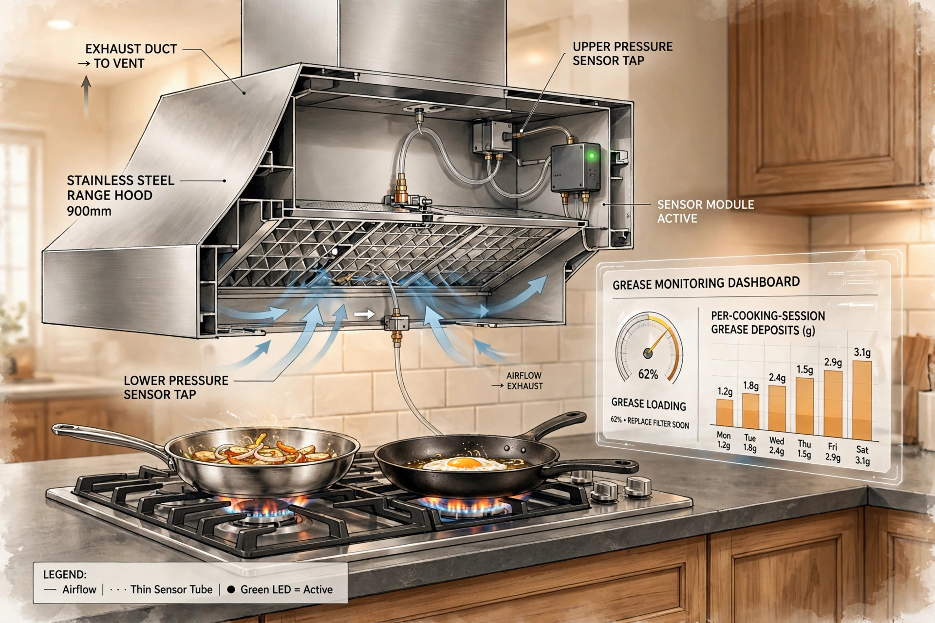
- Figure 1: System diagram showing the range hood cutaway with pressure taps upstream and downstream of the grease filter plane, current sensor and tachometer on the fan motor, cavity microphone, and the on-device processing module with app connection.
- Figure 2: Loading curves plotting normalized differential pressure against accumulated grease mass for mesh, baffle, and charcoal filter types, showing the steep mesh bridging rise, the gradual baffle curve, and the combined charcoal curve, with clean and full-load calibration points marked.
- Figure 3: Fan-curve diagram showing the operating-point slide from the clean point to the loaded point as system resistance rises, with the corresponding current and RPM shifts for PSC and EC motor types.
- Figure 4: Example app dashboard showing the fused loading index gauge, per-session deposit bars for the past week by cook type, the sessions-remaining estimate, and a collection-cup fullness indicator for baffle filters.
Claims
- A system for estimating grease filter loading in a residential kitchen exhaust hood, comprising: a differential pressure transducer with sensing taps positioned upstream and downstream of the grease filter plane; a fan motor current sensor and a tachometer measuring shaft speed; a MEMS microphone positioned in the hood cavity; and a processor configured to compute a normalized loading index from the pressure, current, speed, and acoustic signals.
- The system of claim 1, further comprising a commissioning protocol that learns clean-baseline vectors of differential pressure, motor current, shaft speed, and acoustic band power per fan speed after filter cleaning or replacement, against which subsequent loading is measured as deviation.
- The system of claim 1, wherein the processor computes a pressure loading estimate by normalizing measured differential pressure by the square of shaft speed and comparing the normalized value against clean and full-load calibration values for the installed filter type.
- The system of claim 1, wherein the processor computes an independent current-based loading estimate by mapping measured motor current and shaft speed through a fan-curve segment learned during commissioning to an implied system resistance, and cross-checks the current-based estimate against the pressure-based estimate to detect pressure-tap fouling or filter mis-seating.
- The system of claim 1, wherein the processor computes an acoustic loading estimate from turbulence band power in the 200-2000 Hz range normalized by shaft speed, plus a spectral-centroid shift term, and separately detects filter seating faults from narrowband energy at blade-pass harmonics.
- The system of claim 1, further comprising a per-cook-session deposition model that segments cooking sessions from fan and cooktop activity, classifies each session by cook type as frying, sauté, simmer, or boil/steam, and integrates per-session grease deposition using cook-type-specific deposition rates.
- The system of claim 6, wherein cook type is inferred from cooktop current signatures for electric ranges, from sizzle-band acoustic energy in the 2-8 kHz range for gas cooktops, or from user tagging when inference confidence is low.
- The system of claim 6, further comprising a grease drainage term modeling downward redistribution of deposits under gravity, and, for baffle filters, a collection-cup fullness estimate computed as cumulative baffle grease deposition minus modeled drainage, with an independent cup-full advisory.
- The system of claim 1, wherein the processor selects filter-type-specific loading curves for mesh, baffle, or charcoal filters at commissioning, the mesh curve modeling accelerated pressure rise from grease bridging of mesh openings.
- The system of claim 1, further comprising a tiered advisory module mapping the fused loading index to clean, watch, clean-soon, and clean-now advisories, including a sessions-remaining estimate derived from the household's measured recent deposition rate.
- The system of claim 10, further comprising a fire-risk coupling module that escalates the advisory by one tier and issues a notification when high-heat cooking is detected while the loading index exceeds a threshold.
- The system of claim 1, provided as a retrofit clip-on module drawing power from the hood supply and entering deep sleep when the fan is off, wherein no audio is stored or transmitted and the microphone contributes only on-device band-power and spectral features.
Implementation Notes
Recirculating (ductless) hoods have no exhaust airstream against which to reference differential pressure, so the pressure taps are omitted in that configuration and the estimator runs on the current, acoustic, and deposition-model signals alone, with charcoal saturation tracked by the deposition ledger. Variable-speed DC and EC motors hold RPM under changing load, so the operating-point cross-check uses RPM-normalized current deviation rather than the fixed-speed current shift.
Pressure taps foul. Grease reaches every surface inside a hood eventually, including the inside of a silicone tube, so the design includes a periodic reverse air pulse through the taps during fan-off intervals and flags sustained disagreement between the pressure and current estimates as probable tap fouling rather than averaging the disagreement away. The taps are positioned to avoid direct drip lines from the filter.
Grease viscosity and drainage depend on temperature: a cold kitchen slows drainage and a hot one accelerates it. The deposition model applies an ambient correction from a kitchen temperature reading (from the module's own sensor or a paired thermostat) to the drainage time constant. Multi-filter hoods are handled either with per-filter tap pairs or with a single averaged index, declared at commissioning along with the filter count.
This disclosure is not a fire suppression or fire detection system and does not replace visual inspection or professional duct cleaning. Commercial kitchen exhaust systems governed by NFPA 96 are out of scope; the design targets residential hoods only. All quantitative parameters given as design values are untested engineering choices, labeled as such, and would require empirical calibration before any product implementation.
Prior Art References
- NFPA 96, Standard for Ventilation Control and Fire Protection of Commercial Cooking Operations: inspection and cleaning schedules for commercial kitchen exhaust based on cooking volume; no residential equivalent
- Delp and Singer, Lawrence Berkeley National Laboratory, 2012: fan curves relating airflow to duct static pressure across seven residential hoods; airflow sensitivity to duct resistance higher for axial fans; Environ. Sci. Technol. DOI: 10.1021/es3001079
- CN109030306B: range hood filter screen blockage detection from wind pressure values versus installed reference data; binary blocked-or-not verdict from a single pressure signal, no loading index, no fusion, no deposition model
- CN112762498A: differential pressure sensor detecting oil-stained state of an electrostatic precipitation module to trigger automatic steam cleaning; watches the electrostatic module rather than the grease filter
- EP1979882B1: range hood alarm inferring an excessively soiled grease filter from temperature sensor readings; temperature proxy, no loading measurement
- Carrier weight-based grease monitoring (published application): load cells weighing the hood body to infer grease mass; single-signal mass proxy, no filter-plane sensing or deposition modeling
- US10082299B2: exhaust flow control using a duct pressure transducer for appliance-state detection; flow control, not filter loading estimation
- UL 1046, Standard for Grease Filters for Exhaust Ducts: construction and performance testing of grease filters; does not address in-service loading estimation
- Home Ventilating Institute (HVI): certifies residential range hood airflow and sound performance on clean units; no loading-degradation tracking
- ASHRAE 52.2, Method of Testing General Ventilation Air-Cleaning Devices: dust-loading pressure-drop curves for dry particulate filters; the conceptual basis this disclosure distinguishes from grease aerosol loading
- LITF-PA-2026-137: multi-sensor cooking fire ignition prediction; watches ignition events, distinct from the accumulation tracking disclosed here
- Timer-based filter reminder lights on residential range hoods: elapsed-motor-hour counters that fire after fixed fan runtime regardless of cooking type; measure time, not loading (product observation, no single citable source)