System and Method for Monitoring Residential Water Pressure Regulation Health Using Static Pressure Creep Analysis, Thermal Expansion Transient Signatures, and Relief Valve Discharge Event Detection
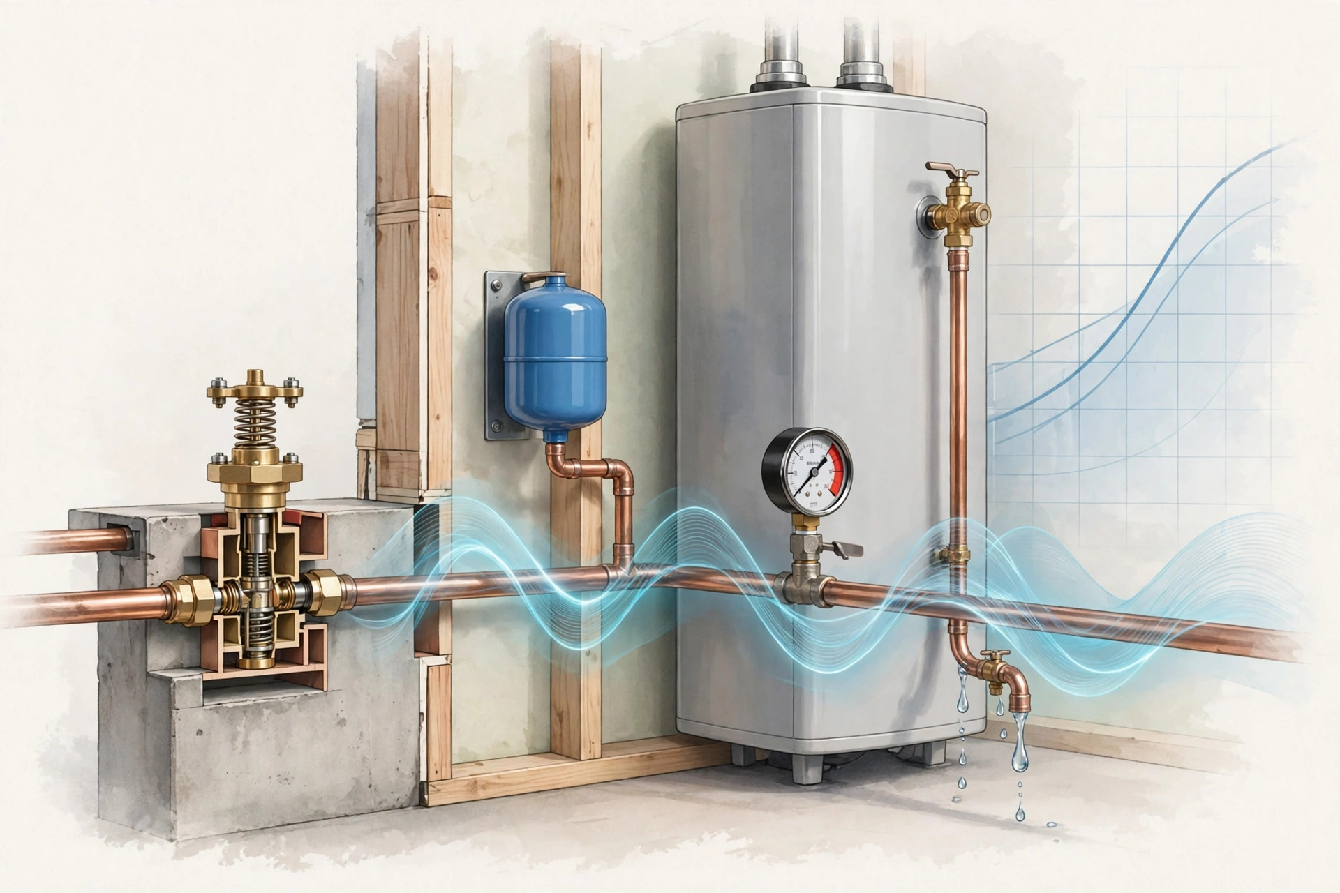
Abstract
Disclosed is a non-invasive system and method for monitoring the health of the three components that regulate residential water pressure: the pressure-reducing valve (PRV), the thermal expansion tank, and the temperature-and-pressure (T&P) relief valve. All three fail silently, and the first symptom is usually water damage. A single pressure transducer on a hose bibb or laundry tap, optionally paired with a pipe-clamp temperature sensor on the water heater outlet and a microphone at the T&P discharge pipe, feeds three diagnostic channels. Overnight static-pressure trending isolates PRV seat and diaphragm wear as a slow pressure creep toward street pressure during quiescent no-flow windows. The pressure rise following each water heater firing cycle quantifies the expansion tank's remaining air cushion through Boyle's-law inversion of the thermal expansion transient, distinguishing a healthy tank from a waterlogged one. Acoustic drip counting at the T&P discharge pipe logs every relief event the safety valve was forced to handle. The fused output attributes each anomaly to its component, producing PRV creep, expansion-cushion, and relief-event indices with replace-now thresholds, so a homeowner learns the PRV is dying or the tank is waterlogged months before a burst supply hose or a flooded utility room.
Field of the Invention
This invention relates to residential plumbing diagnostics, specifically to non-invasive monitoring of water pressure regulation components using pressure transient analysis, thermal expansion signature inversion, and acoustic event detection for predictive maintenance and water damage prevention.
Background
Water damage is the second most common homeowner insurance claim in the United States, accounting for 22.6% of all losses from 2019 through 2023, with about 1 in 60 insured homes filing a water damage or freezing claim each year and an average payout that crossed $15,400 in the most recent five-year window (Insurance Information Institute data via PNW Residences, 2026). Plumbing supply failures are the single largest source of paid water claims, roughly 40% per The Hartford's residential analysis, with plumbing leaks overall at about 45% of incidents (Gitnux, 2026). High system pressure is a force multiplier behind these failures: it accelerates wear on seals, gaskets, appliance solenoid valves, faucet cartridges, and braided supply hoses.
Three components stand between street pressure and the plumbing inside a home. The pressure-reducing valve (PRV) is a spring-loaded diaphragm device on the main water line that steps municipal pressure, which can exceed 100 to 150 psi, down to a house-safe level. PRVs are typically factory set between 50 and 75 psi, the accepted residential range is 40 to 60 psi, and readings above 80 psi indicate the valve may not be functioning (Gray's Precision Plumbing; Grit and Home). PRVs last 10 to 15 years; the internal diaphragm and seat wear, harden, or collect debris. The classic failure signature is pressure creep: with no water in use, the gauge slowly climbs back toward municipal pressure because the worn seat can no longer hold the differential (EngineerFix; Terry Love plumbing forum). Today this is found by a homeowner who happens to own a gauge and happens to check it at 3 AM, which is to say it is never found until something breaks.
Installing a PRV creates a closed system: heated water can no longer push back into the main. Water gains roughly 1.5 to 2 percent in volume over a residential heating rise (Anvil Field guide), and in a closed system that expansion has nowhere to go, so pressure spikes from 50 to 60 psi past 100 psi on every heating cycle. The thermal expansion tank absorbs it: a steel vessel with a rubber bladder separating system water from a precharged air cushion, the precharge set to match the home's static cold-water pressure (mismatched precharge is the number one installation error). The tank fails in two ways: gradual air-charge loss through the Schrader valve, or bladder rupture, both ending waterlogged. The bladder typically lasts 5 to 10 years (Local Hero). The telltale symptom is the T&P relief valve dripping after the heater runs, because without the air cushion each heating cycle drives pressure to the valve's 150 psi setpoint (EngineerFix; EngineerFix). The manual tests are the tap test (healthy tanks sound hollow on top, solid below; waterlogged tanks sound solid throughout) and the Schrader pin test (water spurting out means a ruptured bladder). Both require the homeowner to suspect the tank first.
As the last line of defense, the T&P relief valve opens at 150 psi or 210 degrees F, and it must never be capped, plugged, or valved off (Anvil Field guide). A dripping T&P valve on a closed system is the symptom of trapped thermal expansion, not a faulty valve; replacing the valve without addressing the expansion source guarantees the drip returns.
Existing smart water products monitor for leaks, not regulation-component health. The Moen Flo Smart Water Monitor runs daily pressure-based MicroLeak health tests and FloSense usage learning to catch drips and bursts, and it alerts on high pressure, but it does not trend PRV creep, quantify expansion-tank cushion loss, or attribute pressure anomalies to specific components (EngineerFix; NerdyHomeTech). Phyn Plus uses ultrasonic flow sensing with pressure-wave analysis, and Flume 2 reads the utility meter externally; both target leak detection (NerdyHomeTech). None of them answers the question a homeowner actually needs answered before the damage: which pressure-regulation component is failing, and how fast.
What the art lacks is a complete non-invasive system that separates the three failure modes from a single pressure signal: PRV creep isolated in overnight quiescent windows, expansion-tank cushion quantified from thermal expansion transients via gas-law inversion, and T&P discharge events counted acoustically, fused into component-attributed health indices with actionable thresholds.
Detailed Description
1. Sensing Hardware
In the preferred retrofit embodiment, a battery-powered puck threads onto any hose bibb or laundry tap downstream of the PRV. A piezoresistive pressure transducer (0 to 200 psi range, 0.25% full-scale accuracy, temperature-compensated) samples at 1 Hz continuously and at 10 Hz for 60 seconds around detected events. A pipe-clamp thermistor on the water heater hot outlet (optional but recommended) identifies heating cycles. A MEMS microphone (optional) mounts near the T&P discharge pipe termination to count relief drips. An ESP32-class microcontroller performs event detection and feature extraction on device; only extracted features leave the device. WiFi or BLE carries alerts to a phone app. Target bill of materials is under $40 at volume.
A second embodiment integrates the analytics as a firmware module in an inline smart water monitor of the Moen Flo or Phyn Plus class, reusing its existing pressure sensor and adding the quiescent-window and thermal-transient analysis in software. A third embodiment is a plumber's diagnostic tool: a logging gauge left on the hose bibb for 72 hours that returns a printed regulation-health report at the next visit.
2. Flow-Event Segmentation and Quiescent Window Detection
Every pressure record is segmented into events. Fixture draws appear as rapid pressure drops (5 to 30 psi in under 2 seconds) followed by PRV-regulated recovery; toilet tank fills show a characteristic 60 to 120 second refill plateau; irrigation zones produce long square-wave draws; water softener regenerations appear as scheduled overnight high-flow events and are learned and excluded. A water heater firing is identified by a rising hot-outlet temperature with no concurrent flow draw.
A quiescent window is any continuous period of at least 2 hours with no flow events, typically 1 AM to 5 AM. Only quiescent windows are used for PRV creep analysis, which eliminates fixture-draw transients and municipal demand swings as confounds. Municipal supply pressure itself varies diurnally (often highest overnight), which is exactly why the analysis tracks the trend within each window rather than absolute values: a healthy PRV holds its setpoint flat regardless of rising street pressure, while a worn seat lets the downstream pressure follow the street upward.
3. PRV Creep Analysis
Within each quiescent window, the system fits a linear trend to static pressure after discarding the first 15 minutes (thermal settling). A healthy PRV holds the setpoint within plus or minus 2 psi across the window. A worn seat or fatigued diaphragm produces a monotonic rise, the downstream pressure creeping toward street pressure at a measurable rate. Two metrics are tracked: creep rate (psi per hour, from the window fit) and absolute static level.
Thresholds are staged. A creep rate above 0.5 psi per hour sustained across three or more nights indicates early seat wear: the valve still regulates under flow but no longer seals at zero flow. A creep rate above 2 psi per hour, or any quiescent static reading above 80 psi, indicates a failed regulator requiring replacement. The 80 psi line follows the widely used residential upper limit above which fixture damage risk rises sharply. Creep events are cross-checked against the heater-fire detector so that thermal expansion rises are never misattributed to the PRV: any window containing a heating cycle is excluded from creep scoring and routed to the expansion-tank channel instead.
Inverse failure is also detectable: a PRV whose spring has weakened or whose strainer is clogged shows sagging dynamic pressure (more than 10 psi drop under a 2.5 gpm draw relative to its learned baseline) with normal static pressure, distinguishing flow restriction from regulation failure.
4. Expansion-Tank Cushion Quantification via Thermal Transient Inversion
This is the core measurement. When the water heater fires with no water being drawn, the heated volume expands by a small amount and the system pressure rises. The magnitude of that rise is a direct measure of the compressible air volume remaining in the expansion tank, through Boyle's law. With the tank precharged to static pressure P0 (absolute), air volume V0, and expanded water volume dV entering the tank, the peak pressure P1 satisfies P0 times V0 equals P1 times (V0 minus dV), so the remaining cushion is V0 equals P1 times dV divided by (P1 minus P0).
Estimating the expanded volume dV starts from the heater firing duration and tank size: for a 50-gallon heater, a full 70-degree-F recovery expands roughly 0.6 to 1.0 gallons, while a typical overnight thermostat recovery reheats a fraction of the tank and expands 0.1 to 0.2 gallons. The system does not need dV precisely; it tracks the pressure rise per unit of firing time, which is proportional to 1/V0, so the trend of this normalized rise is the diagnostic. A healthy 2-gallon tank shows under 8 psi rise on a typical overnight recovery. As the air charge leaks or the bladder ruptures, V0 shrinks and the same heating cycle produces a larger spike: 8 to 20 psi indicates a degraded cushion (lost precharge, tank partially waterlogged), and above 20 psi, or any heating cycle that drives the T&P valve to discharge, indicates a failed tank needing replacement.
A worked example grounds the sensitivity. Take P0 at 60 psig (74.7 psia), a 2-gallon tank (V0 equals 2.0 gallons of air at precharge), and an overnight recovery expanding 0.15 gallons. The peak pressure is P0 times V0 divided by (V0 minus dV): 74.7 times 2.0 divided by 1.85, which is 80.8 psia or about 66 psig, a 6 psi rise. If the tank has lost most of its charge and retains only 0.5 gallons of air, the same cycle peaks at 74.7 times 0.5 divided by 0.35, or 106.7 psia (92 psig), a 32 psi rise. The measurement separates healthy from failed with a wide margin, using only a pressure trace the sensor already records.
Commissioning mode runs during the first week after installation. The system learns the home's pressure-versus-accepted-volume curve across several heating cycles. If the curve's knee sits far above cold static pressure, the tank precharge was set too high and the tank does not engage until pressure is already high; if the tank accepts water immediately at static pressure with a soft knee, the precharge is too low and acceptance volume is reduced. Either case produces a one-time "check expansion tank precharge" advisory with the measured static pressure, since precharge mismatch is the most common installation error and it silently degrades every reading the tank will ever produce.
5. T&P Discharge Event Detection
Each T&P discharge is logged as a safety-relevant event. The microphone at the discharge pipe captures drip transients: short 2 to 5 millisecond impacts with energy concentrated between 2 and 6 kHz as water strikes the pipe interior or a drain. A lightweight edge classifier counts these transients during candidate windows flagged by pressure readings above 140 psi (below the 150 psi setpoint, allowing for gauge tolerance) or by hot-outlet temperature anomalies. Each confirmed event is timestamped with its pressure peak and duration.
Event counting is the metric, not single-event alarming: one discharge during an extreme recovery may reflect an unusual but bounded condition, while repeated discharges (more than 2 per month) prove the system is routinely exceeding its design limits and the upstream cause, usually a waterlogged expansion tank or a failed PRV, must be addressed. The disclosure is explicit that the system never commands, interferes with, or depends on the T&P valve's operation; it only observes. Any installation or service guidance states plainly that the T&P valve and its discharge pipe must never be capped, plugged, or valved off.
6. Fusion, Attribution, and Alerting
Fusion combines the three channels into component-attributed health indices on a 0 to 100 scale. The PRV index combines creep rate trend and absolute static level. The cushion index combines normalized thermal rise trend and Boyle-inverted remaining air volume. The relief index counts discharge events per 30-day window. A rules layer resolves combined failures, which are the dangerous cases: a failed PRV feeding street pressure into a system whose expansion tank is also waterlogged produces the fastest escalation to T&P discharge, and the alert text names both components with their measured values ("PRV creeping 1.8 psi/hr overnight, static now 84 psi; expansion cushion down to an estimated 0.4 gallons; T&P discharged 4 times this month").
Alerts are staged: advisory (schedule a plumber within 90 days) for early creep or cushion degradation, replace-soon (within 30 days) for failed thresholds on either component, and urgent (this week) for any T&P discharge pattern or static pressure above 100 psi. Each alert includes the supporting trace: the overnight creep plot, the thermal-rise trend, or the discharge event log, so the homeowner or plumber sees the evidence, not just a score.
7. Confounds and Exclusions
Wells with pressure-tank systems produce pump-cycling pressure sawtooths (typically 40 to 60 psi between cut-in and cut-out); the system detects the sawtooth signature at setup and switches to a well profile where PRV analysis is disabled and the pressure tank's own drawdown is monitored instead. Tankless water heaters store no volume, so thermal expansion transients are an order of magnitude smaller; the cushion channel is disabled and PRV plus relief monitoring continue. Homes with water softeners or whole-house filters upstream of the sensor show regeneration events that are learned and excluded. Irrigation tied in before the PRV is flagged at setup because its pressure is unregulated by definition. Pressure sensor drift is bounded by comparing the sensor's long-term static mean against the PRV setpoint the system learned; a slow common-mode drift of the sensor reads as a setpoint shift and triggers a recalibration prompt rather than a false PRV alarm.
8. Figures Description
- Figure 1: System block diagram showing the hose-bibb pressure puck, optional hot-outlet temperature clamp, optional T&P discharge microphone, on-device event segmentation, the three diagnostic channels, and the fusion and alerting layer.
- Figure 2: Overnight quiescent-window pressure traces for a healthy PRV (flat at setpoint), a wearing PRV (0.8 psi/hr creep), and a failed PRV (static climbing past 80 psi toward street pressure).
- Figure 3: Thermal expansion transient family: pressure rise versus heater firing duration for a healthy 2-gallon tank, a partially waterlogged tank, and a fully waterlogged tank, with the Boyle's-law inversion curve overlaid.
- Figure 4: Worked Boyle inversion example showing remaining air-cushion volume estimated from measured peak pressure across a range of expanded volumes.
- Figure 5: T&P discharge event log: acoustic drip transient waveform, pressure trace crossing 140 psi, and the monthly event-count trend that triggers the relief index.
- Figure 6: Commissioning-mode pressure-versus-accepted-volume curves illustrating correct precharge, excessive precharge (late knee), and insufficient precharge (soft knee, reduced acceptance).
Claims
- A system for monitoring residential water pressure regulation health, comprising: a pressure transducer coupled to a potable water fixture downstream of a pressure-reducing valve; a processor configured to segment the pressure record into flow events and quiescent no-flow windows, fit a static pressure trend within quiescent windows, and compute a pressure-reducing valve health metric from the creep rate of static pressure toward municipal supply pressure during the windows.
- The system of claim 1, wherein the processor excludes from creep analysis any quiescent window containing a water heater firing event, the firing event identified by a rising hot-outlet temperature with no concurrent flow draw.
- The system of claim 1, wherein the pressure-reducing valve health metric applies a first threshold at a creep rate above 0.5 psi per hour sustained across multiple nights indicating early seat wear, and a second threshold at a quiescent static pressure above 80 psi indicating regulator failure.
- A system for quantifying thermal expansion tank air-cushion loss, comprising: a pressure transducer on a closed residential plumbing system; a temperature sensor on a water heater outlet; and a processor configured to detect water heater firing cycles with no concurrent water draw, measure the peak pressure rise of each cycle, and invert the rise through Boyle's law to estimate the remaining compressible air volume in the expansion tank.
- The system of claim 4, wherein the processor normalizes the pressure rise by heater firing duration to produce a firing-normalized rise trend, and wherein a sustained increase in the normalized rise indicates progressive air-charge loss or bladder rupture independent of recovery size.
- The system of claim 4, further comprising a commissioning mode that learns a pressure-versus-accepted-volume curve across initial heating cycles and issues a precharge-mismatch advisory when the curve knee deviates from cold static pressure, indicating incorrect expansion tank air precharge.
- The system of claim 1, further comprising an acoustic sensor at a temperature-and-pressure relief valve discharge pipe, wherein the processor counts drip impact transients correlated with pressure readings above 140 psi to log relief discharge events, and computes a relief index from events per 30-day window.
- The system of claim 7, further comprising a fusion module that combines the pressure-reducing valve health metric, the estimated remaining air volume, and the relief index into component-attributed alerts that name the failing component and report its measured values.
- The system of claim 1, wherein the pressure transducer, processor, and radio are housed in a self-contained unit that threads onto a hose bibb without plumbing modification, and wherein only extracted features and classification results are transmitted, never raw pressure waveforms.
- A method for predictive maintenance of residential water pressure regulation components, comprising: recording static water pressure during overnight quiescent windows; fitting a creep trend to detect pressure-reducing valve seat wear before static pressure exceeds 80 psi; measuring thermal expansion pressure rises after water heater firing cycles and inverting the rises to track expansion tank air-cushion volume; counting temperature-and-pressure relief valve discharge events acoustically; and issuing staged maintenance alerts attributed to the specific failing component.
Prior Art References
- Insurance Information Institute data via PNW Residences, "Water Damage Statistics 2026": Water damage the second most common homeowner claim (22.6% of losses 2019-2023); 1 in 60 homes files per year; average payout above $15,400
- Gitnux, "Water Damage Statistics" (2026): Plumbing leaks at 45% of water damage incidents; plumbing failures the leading cause
- EngineerFix, "How to Adjust and Replace a Residential Pressure Reducing Valve": PRV diaphragm and spring operation; creep toward municipal pressure with no water use as the classic failure signature; 10 to 15 year service life
- Gray's Precision Plumbing, "What Is a Pressure-Reducing Valve (PRV)?": Factory set 50 to 75 psi; street pressure can exceed 150 psi; readings above 80 psi indicate malfunction
- Grit and Home, "Water Pressure Too High? PRV Symptoms and Fixes": 40 to 60 psi ideal residential range; pressure creep and PRV hunting as failure symptoms
- Terry Love plumbing forum, "Pressure Reducing Valve (Regulator) Questions": Field reports of PRV creep from diaphragm and seat wear; expansion tank precharge interaction
- Anvil Field, "Thermal Expansion Tanks and the Closed Plumbing System": Closed systems spike from 50-60 psi past 100 psi per heating cycle; T&P opens at 150 psi / 210 degrees F; precharge must match static pressure; water gains 1.5 to 2 percent volume over a residential rise; never cap the T&P valve
- EngineerFix, "Do Expansion Tanks Go Bad?": Bladder rupture and air-charge loss as failure modes; waterlogging; T&P discharge as the primary symptom
- EngineerFix, "How to Tell If Your Expansion Tank Is Bad": Tap test and Schrader valve test procedures; 5 to 10 year bladder life
- Local Hero, "The Water Heater Expansion Tank": Closed-system definition; pressure climbing from 40-60 psi past 150 psi during heating cycles without a working tank
- EngineerFix, "Moen Flo Reviews": FloSense learning, MicroLeak daily pressure-based health tests; leak-focused, no component-health attribution
- NerdyHomeTech, "Moen Flo Smart Water Monitor": Moen Flo vs Phyn Plus (ultrasonic plus pressure-wave) vs Flume 2 (external meter); all leak-detection oriented
- Boyle's law: For a fixed amount of gas at constant temperature, absolute pressure times volume is constant (P0V0 equals P1V1); the basis for inverting measured pressure rise into remaining air-cushion volume
- International Plumbing Code Section 607.3 / Uniform Plumbing Code Section 608.3: Thermal expansion control required in closed water systems
Implementation Notes
Build notes for whoever implements this. Sensor placement matters more than sensor quality. The hose bibb must be downstream of the PRV; bibbs tied in before the regulator read street pressure and will false-alarm on every municipal swing. The one-minute setup flow asks the user to open a faucet and confirm the sensor sees the draw, which verifies placement in one step. Sample at 1 Hz, not faster, for the continuous record; the 10 Hz burst mode only runs inside event windows, which keeps a year of features in a few megabytes and the radio mostly asleep. The quiescent-window detector needs at least two weeks of history before the first creep verdict, because a single night of high street pressure is weather, not wear; the trend across nights is the signal. Do not ship the PRV index without the heater-fire gate. Every closed-system home produces thermal expansion rises that look exactly like creep to a naive trend fitter, and the number one support ticket will be "your app says my PRV is failing" from a home with a waterlogged tank. The two channels exist to exonerate each other, and the fusion rules should say so in the alert text. For the Boyle inversion, do not present the air-volume estimate as a calibrated measurement; present it as an index with the worked-example math in the app's explainer, because dV is estimated, not measured. The honest claim is the trend, not the absolute gallons. On well systems, say so at setup and disable the PRV channel entirely rather than tuning thresholds around pump sawtooths. On the T&P channel, the microphone is optional hardware; without it, pressure-only event logging (peaks above 140 psi with no flow) still catches most discharges, just without drip confirmation. Never, in any embodiment or marketing copy, suggest that monitoring substitutes for the T&P valve's safety function, and never provide instructions for adjusting a T&P valve's setpoint. The product measures the pressure regulation system; a licensed plumber repairs it. That line belongs in the manual verbatim.