System and Method for Predicting Water Pipe Freeze Events Using Acoustic Velocity Thermometry with Distributed Temperature Inference
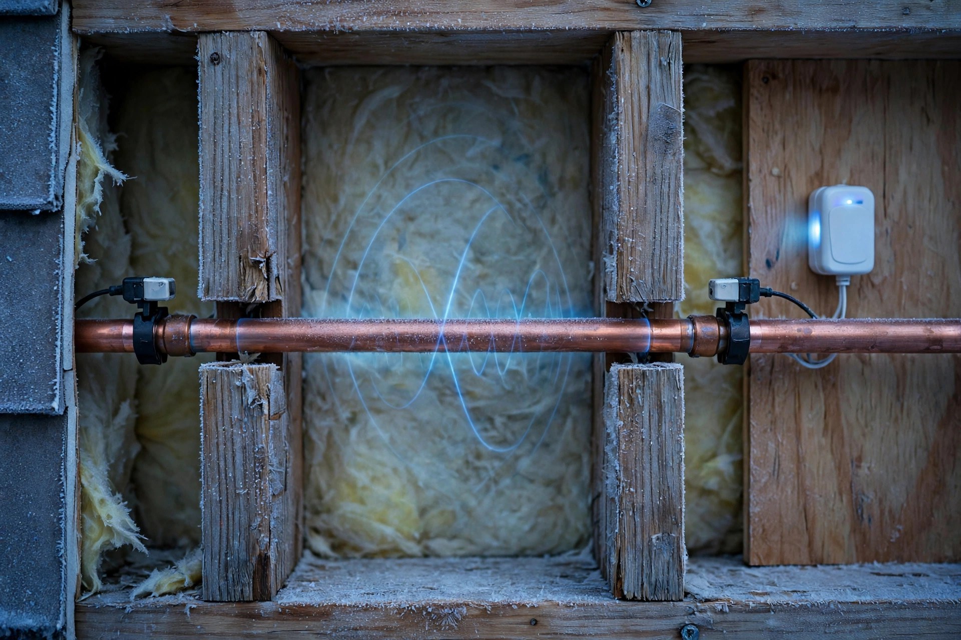
The water inside your walls is colder than the thermostat says, and nobody measures it. Every freeze alarm on the market measures the air or the pipe wall and guesses at the water. This disclosure measures the water itself, without cutting the pipe: sound crosses water at 1,402 meters per second at freezing and 1,482 at room temperature, so a clamp-on ultrasonic sensor can read the water temperature to a fraction of a degree from outside the pipe and warn hours before the first ice forms.
Abstract
Disclosed is a system and method for predicting water pipe freeze events by measuring the temperature of the water inside a pipe directly, without penetrating the pipe wall, using acoustic velocity thermometry. A pair of clamp-on ultrasonic transducers mounted on opposite sides of a pipe measures the transit time of an ultrasonic pulse across the water column. Because the speed of sound in fresh water rises steeply with temperature near freezing, from 1,402 m/s at 0 °C to 1,447 m/s at 10 °C, the measured transit time inverts to water temperature with sub-degree resolution. The system detects the onset of ice formation from the abrupt change in received waveform amplitude and arrival time caused by the acoustic impedance mismatch between water and ice, infers flow state from differential transit time between upstream and downstream paths, and fuses the measured water temperature with cavity air temperature, weather forecasts, and a learned thermal model of the pipe run to project time-to-freeze. On crossing a risk threshold the system triggers mitigation, including opening a smart valve to drip, energizing heat tape, or alerting the owner to shut off and drain the run.
Every freeze alarm on the market measures the air or the pipe wall and guesses at the water. This one measures the water.
- $15,400 is the average water damage and freezing claim, 2019 to 2023, per the Insurance Information Institute.
- 22.6% of all homeowners insurance claims in that period were water damage or freezing, second only to wind and hail.
- 1.5 per 100 insured house-years filed a water damage or freezing claim each year from 2019 to 2023, about 1 home in 67.
- 1,402 vs 1,482 m/s: the speed of sound in fresh water at 0 °C vs 20 °C. That 80 m/s slope is the thermometer.
- About 50 nanoseconds is the transit-time shift per °C across a 20.2 mm water path near freezing, against time-to-digital converters that resolve picoseconds.
- 9% is how much water expands when it freezes. Ice plugs trap liquid water between them, and the trapped water has nowhere to go, so pressure rises until the pipe splits.
- $35 to $60 in parts is one sensing node in volume, an estimate, and install takes about ten minutes with no plumber and no water shutoff.
Send this to someone with pipes in an exterior wall.
Field of the Invention
This invention relates to residential plumbing protection, specifically to non-invasive measurement of water temperature inside a pipe and prediction of freeze events using ultrasonic transit-time thermometry, ice-onset acoustic detection, and thermal modeling of pipe runs in cold-exposed building cavities.
Background
Frozen pipes are one of the most common and most expensive home insurance claims in the United States. Water damage and freezing accounted for 22.6% of all homeowners insurance claims from 2019 to 2023, at about 1.5 claims per 100 insured house-years, with an average claim of about $15,400 (Insurance Information Institute, citing ISO/Verisk data). The damage is not caused by the ice itself. Water expands by about 9% when it freezes, and ice plugs that form at two points along a run trap liquid water between them; as that trapped water freezes, pressure rises until the pipe splits, often at a fitting meters away from the ice. A burst supply line can release hundreds of gallons per hour into a wall cavity, and the leak is frequently discovered only when water appears through a ceiling or a floor, hours later.
Every freeze alarm sold today measures something other than the water. The established designs fall into three groups, and each one guesses:
- Ambient air sensors: A thermostat or a battery sensor in the room or crawl space alarms when air temperature falls below a set point. The water in the pipe lags the air by hours, and the lag depends on pipe material, diameter, insulation, and whether water is flowing, so an air reading is a poor proxy for the water. US4800371A (Arsi, 1989, expired) is the classic form: it senses ambient air near the pipe and sounds an alarm when air temperature implies the water has reached about 4 to 5 °C, using an experimentally determined air-to-water offset of roughly -1 to -15 °C of air for 4 to 5 °C of water. The patent itself concedes the inference is indirect.
- Pipe-wall contact sensors: A thermistor or thermocouple strapped to the outside of the pipe, sometimes under insulation. Wall temperature tracks water temperature more closely than air does, but it is biased by contact quality, by insulation compression at the sensor, and by the thermal mass of the pipe wall itself. During a rapid cold snap the wall can read several degrees colder than the water it contains, which produces false alarms, or warmer, which produces missed freezes. KR20150030120A and related filings compare pipe temperature, water temperature, and ambient temperature against stored thresholds, but the water temperature in those systems is still measured at the wall or inferred, not measured in the water column.
- Pressure-based freeze state inference: EP3850163B1 determines the state of water in a pipe, including a prediction that it will freeze, by analyzing pressure inside the plumbing as a function of time. Pressure responds to freezing only after ice has already formed and begun to constrict the run, so it detects a freeze in progress rather than predicting one hours ahead. US20170138023 detects a freezing onset event from a temperature profile, specifically the characteristic drop-then-rise of a temperature trace as latent heat is released when water begins to freeze, and triggers an alarm or a recirculation pump. That method still depends on a wall or air temperature sensor, and it fires at the moment freezing starts, not before.
Clamp-on ultrasonic transit-time flow meters are established commercial instruments. They measure flow by timing ultrasonic pulses upstream and downstream along a diagonal path through the pipe, and they infer flow velocity from the difference in transit times. The same hardware, run in a different mode, can measure temperature: the absolute transit time across the water column depends on the speed of sound in the water, and the speed of sound in water depends strongly on temperature. What does not exist is a system that uses that dependence as a thermometer for freeze prediction, that detects ice onset acoustically, and that fuses the direct water temperature with flow state and a thermal model to project time-to-freeze. That is the gap this disclosure addresses.
The physics is settled and the numbers are favorable. The speed of sound in pure fresh water at atmospheric pressure is 1,402 m/s at 0 °C, 1,447 m/s at 10 °C, 1,482 m/s at 20 °C, and 1,509 m/s at 30 °C, described by the Bilaniuk and Wong polynomial (J. Acoust. Soc. Am. 1993, erratum 1996), fitted to Del Grosso and Mader data. Near freezing the slope is about 4.5 to 5.0 m/s per °C. On a 3/4-inch Type L copper pipe with an internal diameter of about 20.2 mm, the transit time across the water column is about 14.4 microseconds at 0 °C and about 14.0 microseconds at 10 °C, a shift of roughly 44 nanoseconds per °C. Commercial time-to-digital converters resolve well under 100 picoseconds, so the electronics are not the limit. The limit is knowing the exact acoustic path length and separating the water-borne arrival from the faster wall-borne arrival, and this disclosure addresses both.
Detailed Description
1. Clamp-On Transducer Assembly
Each sensing node comprises two piezoelectric ultrasonic transducers, nominal center frequency 1 to 2 MHz, mounted in a spring-loaded clamp that holds them against opposite sides of the pipe on a diametral line, with an acoustic coupling gel or a dry elastomer coupling pad between each transducer face and the pipe wall. The clamp fits standard residential pipe sizes from 1/2-inch to 1-inch nominal diameter in copper, PEX, and CPVC, with the pipe outer diameter entered at install or measured by the clamp jaws. A single-board controller drives the transmit transducer with a short tone burst, typically 3 to 5 cycles, and digitizes the received waveform at the opposite transducer. The node draws under 1 watt peak and averages a few milliwatts at one measurement per minute, runs from a wall adapter or a battery with a multi-year life, and reports over Wi-Fi, Bluetooth Low Energy, or a sub-GHz mesh to a home hub. No cutting, draining, or soldering is required at install. The transducers never touch the water.
The received waveform contains two arrivals. The wall-borne arrival travels through the pipe wall itself, at roughly 4,700 m/s in copper and 5,900 m/s in steel but only about 1,500 to 2,200 m/s in PEX and CPVC, and in metal pipe it reaches the receiver first. The water-borne arrival travels through the wall, across the water column, and back through the wall, and arrives later. The controller separates them by time gating: the water-borne arrival is expected in a window computed from the pipe geometry and the plausible range of water sound speeds, 1,400 to 1,550 m/s, and the first arrival inside that window is the measurement. Where the wall is thin relative to the water path, as in copper, the separation is several microseconds and the gating is straightforward. Where the wall is thick and slow, as in PEX, the arrivals are closer together, and the controller uses the known wall thickness and material sound speed, entered at install, to predict the wall arrival time and subtract it. A reference measurement at install, taken while the pipe is at a known temperature verified by a temporary contact thermometer on an accessible section of the same run, calibrates the effective acoustic path length for that node, absorbing manufacturing tolerances in the clamp and the pipe.
2. Transit-Time Measurement and Temperature Inversion
Each measurement cycle fires the transmit transducer and records the received waveform. The controller measures the transit time of the water-borne arrival by cross-correlating the received waveform against the transmitted burst template and taking the peak of the correlation envelope, with parabolic interpolation between samples for sub-sample resolution. Averaging 16 to 64 pulses per measurement suppresses noise and averages out microbubble scattering. The measured transit time t, the calibrated effective path length L, and the relation c = L / t give the speed of sound in the water. Temperature follows by inverting the Bilaniuk and Wong polynomial, or equivalently a lookup table of sound speed against temperature at 0.1 °C intervals, interpolated linearly. The inversion is single-valued over the 0 to 30 °C range of interest, because sound speed in water rises monotonically with temperature in that range.
Two error sources dominate, and both are handled by calibration rather than by assuming them away. First, the effective path length changes slowly with scale buildup on the pipe interior and with clamp creep, so the node re-calibrates opportunistically on known-temperature events. After a hot-water draw, the water in the hot run sits near the water heater setpoint, typically 49 to 60 °C, and the node records the transit time at that known temperature and updates its path-length estimate. After a long stagnation on the cold run, the water approaches the municipal supply temperature, which the hub can cross-check against utility-reported supply temperature where the utility publishes it. Second, the water in a horizontal pipe is not isothermal: water is densest at about 4 °C, so between 0 and 4 °C the coldest water is the least dense and sits at the top of the pipe, and a diametral measurement reads a path-averaged temperature, not the coldest layer. The disclosure states this plainly: the reported temperature is a path average, and the freeze threshold is set with a safety margin, typically alarming when the path-averaged temperature falls below 2 °C, to account for a colder layer at the top of the pipe. A vertical pipe run, where stratification is minimal, is the preferred install location where one is available.
| Water temperature | Speed of sound | Transit time, 20.2 mm path |
|---|---|---|
| 0 °C (freezing) | 1,402 m/s | 14.41 µs |
| 2 °C (alarm threshold) | 1,412 m/s | 14.30 µs |
| 5 °C | 1,426 m/s | 14.16 µs |
| 10 °C | 1,447 m/s | 13.96 µs |
| 20 °C (room temperature) | 1,482 m/s | 13.63 µs |
The table shows why the method works best exactly where it matters. The transit-time shift per degree is largest near freezing, about 46 to 53 nanoseconds per °C between 0 and 5 °C, and the measurement hardware resolves picoseconds, so the temperature resolution of the electronics is roughly a thousand times finer than the 0.1 °C the application needs. The practical accuracy, after path-length calibration and stratification margin, is estimated at plus or minus 0.5 °C. That estimate is unvalidated: no prototype of this system has been built, and the number is a design target, not a measured result.
3. Ice-Onset Detection
Temperature alone cannot distinguish water at 0 °C from water that has begun to freeze, and the distinction matters, because a pipe with a thin ice layer can still be saved by flow or heat while a pipe with a full ice plug cannot. The node therefore watches the received waveform itself for the signature of ice. Ice has a longitudinal sound speed near 3,800 to 4,000 m/s and an acoustic impedance near 3.5 MRayl, against water at 1.48 MRayl, so a water-ice interface reflects roughly 40% of the incident acoustic energy. When ice first forms on the inner pipe wall, three things happen to the received signal at once: the water-borne arrival loses amplitude as energy is reflected and scattered at the ice layer, its arrival time shifts earlier as part of the path is replaced by faster ice, and a new early reflection appears from the ice front. The controller tracks received amplitude, arrival time, and waveform shape against the baseline established during the preceding hours, and flags ice onset when amplitude falls by more than 25% from baseline while arrival time shifts by more than 100 nanoseconds earlier, or when a distinct early reflection appears. Either condition, combined with a measured water temperature at or below 1 °C, raises the highest alert tier. The thresholds are proposed values, unvalidated, and the disclosure claims the detection method, not the specific numbers.
Ice onset also changes the pipe mechanically in a way the same transducers can hear. The first ice layer stiffens the pipe wall locally, which shifts the resonant frequency of the wall-borne arrival. The controller measures the wall-borne arrival spectrum on every cycle and reports a shift of more than 2% from baseline as corroborating evidence of ice formation. This is a secondary channel, weaker than the water-borne amplitude and arrival test, and it never triggers an alert on its own.
4. Flow-State Inference from Differential Transit Time
Whether water is flowing changes everything about freeze risk. Flowing water brings in warmer water from the heated interior of the house, and a run with regular flow almost never freezes even when the cavity around it is below freezing. Stagnant water cools toward the cavity temperature and is the water that freezes. The node therefore measures flow with the same transducers, in a second mode: it fires pulses in both directions along a diagonal path between two transducer pairs offset along the pipe axis, and the difference in upstream and downstream transit times gives flow velocity, exactly as in a clamp-on ultrasonic flow meter. A measured flow velocity below 0.01 m/s for 30 minutes classifies the run as stagnant. The thermal model in section 5 uses stagnant and flowing states differently, and a run that has been stagnant for more than 6 hours during a cold snap is escalated one risk tier even if its measured temperature has not yet crossed the alarm threshold.
Flow also provides a second calibration opportunity. When a tap opens, cold supply water at a known municipal temperature, or hot water at the heater setpoint, sweeps through the run, and the node observes a step change in measured temperature toward a known value. The hub records these steps as calibration events and uses them to track path-length drift over months, which is how the system stays accurate without a service visit.
5. Thermal Model and Time-to-Freeze Projection
A temperature reading is a snapshot. A freeze warning needs a projection, so the hub runs a thermal model for each instrumented run. The model is first-order: the water temperature follows the cavity air temperature with a time constant tau that depends on pipe material, diameter, insulation, and flow state. Rather than assuming tau from tables, the hub learns it. During the first cold snap after install, the hub fits tau from the observed response of measured water temperature to measured cavity air temperature, separately for flowing and stagnant states, and refits after any change in insulation or pipework. The node measures cavity air temperature with a small thermistor on the hub-facing side of the clamp, and the hub pulls the weather forecast for the property address, so the model projects water temperature forward over the next 24 hours under the forecast air temperatures. Time-to-freeze is the projected time at which the water temperature reaches 0 °C under the forecast, assuming the current flow state persists. The alert tiers are set on time-to-freeze, not on temperature alone: more than 12 hours is Watch, 4 to 12 hours is Act Soon, under 4 hours is Act Now, and detected ice onset is Emergency regardless of the projection. The tier boundaries are proposed values.
The model is honest about its uncertainty. The projection carries a confidence interval derived from the scatter of the tau fit and the spread of the forecast, and the hub reports the interval alongside the point estimate. A projection whose lower confidence bound reaches 0 °C within 4 hours escalates the tier even when the point estimate is later, because a freeze warning that arrives late is worse than one that arrives early. Where the forecast is unavailable, the model holds the current cavity temperature constant and labels the projection as a steady-state estimate, not a forecast.
6. Multi-Node Placement and Per-Segment Risk Scoring
A house has several runs at risk, and they are not equally at risk. Nodes are placed at the segments most exposed to cold: runs in exterior walls, especially north-facing walls, runs in unheated crawl spaces and garages, attic runs, and runs near foundation vents or gaps in insulation. Each instrumented segment gets a risk score from three factors: measured water temperature and its rate of fall, the learned tau for that segment, and a static exposure factor from the install survey, including wall orientation, insulation thickness, and distance from the heated envelope. The hub ranks segments by risk score and presents the worst segment first, so the owner sees one number and one location, not a dashboard of sensors. In a vacant home the ranking drives an automated response: the hub can command a smart main shutoff valve and open a drain, which is the only mitigation that works when nobody is home to drip a tap.
Nodes also corroborate each other. A segment whose measured temperature falls far faster than its neighbors, with no corresponding fall in cavity air temperature, indicates a local problem: a missing insulation batt, an open vent, or a draft from a penetration gap. The hub flags the anomaly and suggests a physical inspection of that wall section, which is a repair that pays for itself in the next cold snap whether or not a freeze was imminent.
7. Mitigation Actions
On crossing a tier threshold the hub acts in order of increasing disruption. At Watch it sends a notification with the segment, the measured temperature, and the projected time-to-freeze. At Act Soon it opens a smart valve on the affected run to a drip, typically 0.5 to 1 liter per minute, which keeps water moving and brings in warmer water, and it sends a notification naming the tap that is dripping. At Act Now it energizes heat tape on the run where heat tape is installed, increases the drip rate, and notifies the owner and, where the owner has opted in, a designated neighbor or property manager. At Emergency, on detected ice onset, it shuts the main supply valve, opens the drain on the affected run where an automated drain exists, and alerts the owner immediately, because a frozen pipe that thaws while the supply is open is the pipe that floods the house. Every automated action is logged with a timestamp and a reason, and the owner can disable any action class in advance. The hub never opens a valve or energizes heat tape in a home where the owner has disabled automation, and it says so in the alert instead.
8. Figures Description
- Figure 1: System architecture showing clamp-on transducer nodes on pipe runs in an exterior wall, crawl space, and attic, reporting to a home hub that pulls weather forecasts and issues alerts and mitigation commands.
- Figure 2: Speed of sound in fresh water against temperature from 0 to 30 °C, with the near-freezing slope annotated, and the corresponding transit time across a 20.2 mm water path.
- Figure 3: Received waveform at the transducer pair showing the wall-borne arrival, the time gate, and the water-borne arrival, with the shifted and attenuated waveform after ice onset overlaid.
- Figure 4: Thermal model projection showing measured water temperature, cavity air temperature, and forecast air temperature over 24 hours, with the projected time-to-freeze and its confidence interval marked.
- Figure 5: Per-segment risk ranking for a house with four instrumented runs, showing temperature, rate of fall, learned time constant, and exposure factor for each.
Claims
- A system for predicting water pipe freeze events, comprising: a pair of ultrasonic transducers clamped to opposite sides of a pipe without penetrating the pipe wall; a controller that measures the transit time of an ultrasonic pulse across the water column inside the pipe; and a temperature inversion module that converts the measured transit time to water temperature using the temperature dependence of the speed of sound in water.
- The system of claim 1, wherein the temperature inversion uses the Bilaniuk and Wong polynomial or a lookup table derived from it, and wherein the effective acoustic path length is calibrated at install against a known-temperature reference and re-calibrated opportunistically on known-temperature events including hot-water draws at the water heater setpoint.
- The system of claim 1, further comprising an ice-onset detector that flags ice formation when the received waveform amplitude falls by more than 25% from baseline while the water-borne arrival time shifts earlier by more than 100 nanoseconds, or when a distinct early reflection appears from an ice front, combined with a measured water temperature at or below 1 °C.
- The system of claim 1, further comprising a flow-state module that measures flow velocity from differential upstream and downstream transit times along a diagonal path, classifies the pipe run as stagnant below a velocity threshold, and escalates freeze risk for a stagnant run during a cold snap.
- The system of claim 1, further comprising a thermal model that learns a time constant for the pipe run from observed water temperature response to cavity air temperature, projects water temperature forward under a weather forecast, and reports a projected time-to-freeze with a confidence interval.
- The system of claim 5, wherein alert tiers are set on projected time-to-freeze rather than on measured temperature alone, and wherein a projection whose lower confidence bound reaches 0 °C within a threshold time escalates the tier.
- The system of claim 1, further comprising a plurality of sensing nodes placed on distinct pipe segments, each segment scored by measured temperature, rate of temperature fall, learned time constant, and static exposure, with segments ranked by risk and the worst segment presented first.
- The system of claim 1, further comprising a mitigation module that, on crossing a risk threshold, opens a smart valve to drip, energizes heat tape, or shuts the main supply valve and opens a drain, with each automated action logged and individually disableable by the owner.
- A method for predicting a water pipe freeze event, comprising: clamping an ultrasonic transducer pair to opposite sides of a pipe; measuring the transit time of an ultrasonic pulse across the water column; converting the transit time to water temperature by inverting the speed of sound in water against temperature; projecting time-to-freeze from the measured temperature, its rate of change, and a weather forecast; and triggering a mitigation action before the water reaches 0 °C.
- The method of claim 9, further comprising detecting ice onset from a change in received waveform amplitude and arrival time, and on detecting ice onset, shutting the main supply valve before the pipe thaws.
Implementation Notes
Bill of materials per node is estimated at $35 to $60 in volume: two piezoelectric transducers, a time-to-digital converter or a microcontroller with a high-resolution timer peripheral, a clamp housing, coupling pads, and a radio. The hub is a commodity single-board computer or an existing smart home hub running the thermal model and forecast fetch. Install takes about ten minutes per node by a homeowner: clean the pipe, apply coupling gel, close the clamp, and enter the pipe material and diameter in the app. No plumber is required, and no water is shut off. Battery life at one measurement per minute is estimated at two to three years on two AA lithium cells; mains power is preferred where an outlet is within reach, because the flow-measurement mode fires more pulses and draws more current.
Pipe material matters. Copper couples well and its thin wall separates cleanly from the water arrival. PEX has a thicker, slower wall, so the wall-borne and water-borne arrivals sit closer together and the controller needs the wall thickness and material sound speed entered at install to gate correctly. CPVC sits between the two. Galvanized steel is the hardest case: the wall is thick, the sound speed in steel is high, and internal corrosion roughens the reflecting surface, which scatters the pulse. The disclosure claims the method for all four materials and states that steel is the least favorable. A node that cannot separate the arrivals on a given pipe reports low signal quality and does not issue temperature readings, rather than issuing a wrong one.
Limitations
This disclosure describes an unbuilt system. No prototype has been constructed, no accuracy figure has been measured, and every threshold in it is a proposed value. The plus or minus 0.5 °C accuracy figure is a design target derived from the transit-time arithmetic, not a measured result. The stratification problem is real and unresolved: a diametral measurement reads a path average, and the coldest water in a horizontal pipe near freezing sits at the top, so the path average overstates the temperature of the layer that freezes first. The 2 °C alarm threshold is a margin against that bias, and the margin is a guess. Dissolved gas, microbubbles from a recent draw, and entrained air after plumbing work all scatter ultrasound and can corrupt a measurement; the controller rejects corrupted cycles by waveform quality, but a run that produces corrupted cycles for hours reports no temperature rather than a wrong one. A drained pipe has no water column and no water-borne arrival, so the node reports the run as dry and cannot assess freeze risk, which is the correct answer for a drained pipe but means the system cannot distinguish a drained run from a failed sensor without a manual check. Finally, the system protects only the runs it instruments. A freeze in an uninstrumented branch is invisible to it, and the per-segment risk ranking is only as complete as the install survey.
Strongest Case Against
The honest objection is that a $15 thermistor taped to a pipe, plus a weather forecast, already prevents most freezes, and this system is a more expensive answer to a problem that cheap sensing mostly solves. For accessible pipes, that objection is correct: where you can reach the pipe, a contact sensor is cheaper, simpler, and easier to trust. The acoustic method earns its cost only in three cases: pipes behind finished walls that cannot be reached without demolition, pipes in homes that sit vacant for weeks where an early warning has to be right the first time, and the detection of actual ice formation, which no thermistor can do. If the market for those three cases is small, the system is a niche product, and this disclosure does not pretend otherwise. A second objection is that the temperature being measured is a path average, not the coldest layer, which blunts the precision the transit-time arithmetic promises. The 2 °C alarm margin is an admission of that, not a solution to it. Both objections are fair, and both are stated here so that anyone building on this disclosure starts from them rather than discovering them later.
What a Homeowner Can Do Now
None of this needs to be built before it helps. If a cold snap is coming, open the cabinet doors under sinks on exterior walls so warm room air reaches the pipes, let faucets on exterior-wall runs drip at a thin steady stream, and keep the thermostat at one temperature day and night rather than setting it back. Know where the main water shutoff is before you need it, and shut off and drain outdoor hose bibs and any run serving an unheated space you will leave vacant. Insulate exposed runs in crawl spaces and attics with foam sleeves, and seal the gaps where pipes pass through the exterior wall, because the draft through a penetration gap cools a pipe faster than still cold air does. If a pipe does freeze, shut off the main supply first, then thaw gently with warm air, and never use an open flame. A frozen pipe that thaws with the supply open is the one that floods the house.
Prior Art References
- US4800371A: Arsi, Freeze alarm sensing ambient air temperature near the pipe (1989, expired)
- EP3850163B1: Freeze prediction, detection, and mitigation using pressure as a function of time
- US20170138023: Managing a fluid condition in a pipe; freezing onset from temperature profile and latent-heat plateau
- KR20150030120A: Freeze protection system comparing pipe, water, and ambient temperatures against stored thresholds
- National Physical Laboratory: Speed of sound in pure water; Bilaniuk and Wong equations (1993, erratum 1996)
- NOAA: Speed of sound in water; 1,402 m/s at 0 °C, 1,482 m/s at 20 °C
- Bilaniuk, N., and Wong, G. S. K. (1993). Speed of sound in pure water as a function of temperature. J. Acoust. Soc. Am. 93(3), 1609-1612; erratum (1996), J. Acoust. Soc. Am. 99(5), 3257.
- Insurance Information Institute, via This Old House: Water damage and freezing: 22.6% of homeowners claims 2019-2023, 1.5 claims per 100 house-years, average claim $15,400
- American Red Cross: Preventing and thawing frozen pipes
- Insurance Institute for Business & Home Safety: Winter Ready guidance for freeze prevention
- LORRIC: Speed of sound in water temperature table; ultrasonic flow meter practice
- WO2007040305: Piping system with functions of preventing water leakage and freezing using temperature sensors and heating wires