System and Method for Refrigerant Charge Loss Detection in Vapor-Compression HVAC Systems Using Non-Invasive Pipe-Surface Thermometry, Compressor Electrical Signature Analysis, and Duty-Cycle Drift Monitoring
Abstract
Disclosed is a system and method for detecting refrigerant charge loss in residential and light-commercial vapor-compression air conditioners and heat pumps without pressure gauges and without any intrusion into the sealed refrigerant circuit. A retrofit sensor kit combines three non-invasive measurement channels: clip-on pipe-surface thermistors on the suction and liquid refrigerant lines, a split-core current transformer on the outdoor unit electrical feed, and compressor runtime data from the thermostat or a current-sensing runtime logger. An edge hub computes virtual superheat and subcooling proxies from surface temperatures alone, tracks steady-state compressor current, and monitors duty-cycle drift against an adaptive per-installation baseline learned during a commissioning window. A fault-decoupling module separates the charge-loss signature (falling subcooling proxy, rising superheat proxy, declining compressor current, lengthening runtimes) from confounders with overlapping symptoms: low indoor airflow, fouled condenser coils, liquid-line restrictions, and expansion-valve faults. A graduated response reports estimated efficiency loss and added energy cost at the watch tier, issues a charge-loss alert with supporting evidence at the alert tier, and recommends compressor-protective service action when thermal stress indicators cross critical thresholds.
Technical Field
This disclosure relates to heating, ventilation, and air conditioning (HVAC) diagnostics, specifically to continuous non-invasive monitoring of refrigerant charge state in vapor-compression systems using surface thermometry, electrical signature analysis, and runtime telemetry fused at the edge.
Background
Improper refrigerant charge is one of the most common and most expensive faults in installed air conditioning. Field studies summarized by Purdue researchers found that more than half of installed residential and light-commercial systems operate with incorrect charge from bad commissioning, service errors, or slow leakage (Li and Braun, ACEEE 2008). An undercharged system loses capacity, runs longer to meet the thermostat setpoint, and consumes 10 to 20 percent more electricity for the same cooling. Compressors suffer too: low charge starves the compressor of cool suction vapor, discharge temperatures climb, and lubricant return degrades, shortening compressor life. Leaked refrigerant also carries a climate cost. Common refrigerants such as R-410A have global warming potentials in the thousands, so a slow leak is both an energy problem and an emissions problem.
Charge is invisible to the homeowner. There is no direct charge gauge on a residential system; the only exact measurement is to recover the full charge and weigh it, a procedure that requires a vacuum pump, a scale, and a service call. In practice technicians infer charge from superheat and subcooling: superheat is the suction-line temperature minus the evaporating saturation temperature, and subcooling is the condensing saturation temperature minus the liquid-line temperature. Saturation temperatures come from pressure readings through manifold gauges connected to the service ports. Every gauge connection risks a small refrigerant release and introduces a potential leak point at the Schrader cores. Homeowners therefore learn about charge problems only through the electric bill, weak cooling on the hottest week of the year, or a dead compressor.
Researchers have attacked the gauge problem for two decades. Li and Braun at Purdue demonstrated a virtual refrigerant charge sensor using four surface-mounted temperature measurements taken while the system runs at steady state, estimating charge without any pressure transducer (Li and Braun, ACEEE 2008; NYSERDA/ORNL visual fault detector program). Follow-on work built complete fault detection and diagnosis for rooftop units around such virtual sensors (Kim, Purdue dissertation 2014). These are laboratory-validated techniques, not consumer products. They assume controlled steady-state conditions, technician-placed sensors, and a known-healthy reference.
Equipment makers embed charge diagnostics in premium hardware. Emerson holds patents on HVAC remote monitoring and refrigerant charge verification (US10488090B2, US9765979B2), and Carrier on self-charging and charge monitoring (US9759465B2). These systems are factory-integrated into the equipment: they use in-circuit pressure or temperature sensors installed at manufacture and are unavailable as retrofits for the hundreds of millions of already-installed units. Patent filings also cover leak detection without pressure sensors in narrow forms: US20170355246A1 detects leakage from temperature-sensor patterns and triggers a refrigerant isolation valve, WO2021050704A1 compares subcooling, superheat, power, and compressor speed against expected values inside the equipment controller, and US11578887B2 computes superheat from in-circuit evaporator sensors. Each of these is either built into new equipment or relies on sensors inside the refrigerant circuit.
The gap in the art is a complete deployable system that: (a) retrofits to any installed split system or packaged unit with zero intrusion into the refrigerant circuit and zero pressure sensors, (b) fuses three independent non-invasive channels (pipe-surface thermometry, compressor electrical signature, thermostat duty cycle) so that no single drifting sensor can trigger a false charge-loss verdict, (c) self-calibrates to each specific installation through a commissioning baseline instead of requiring factory charge tables or a technician visit, (d) actively decouples charge loss from the four faults that mimic it, and (e) converts the diagnosis into homeowner-actionable tiers with estimated energy cost and compressor-risk framing.
Detailed Description
1. Charge-sensitive quantities in the vapor-compression cycle
A split air conditioner moves heat through four components in a loop. Inside the loop, the compressor pressurizes refrigerant vapor and sends it through the discharge line to the outdoor condenser coil, where it rejects heat and condenses to liquid. From the condenser, the liquid line carries it to the expansion device (a thermostatic expansion valve, TXV, or a fixed orifice), which drops its pressure before the indoor evaporator coil, where it absorbs heat and evaporates; the suction line then returns vapor to the compressor.
Two derived quantities govern charge diagnosis. Superheat is the temperature of vapor leaving the evaporator above its saturation temperature; it measures how completely the evaporator is fed. Subcooling is the temperature of liquid leaving the condenser below its saturation temperature; it measures how much liquid is stacked in the condenser. When charge leaks out, the condenser holds less liquid, so subcooling falls; the evaporator starves, so superheat rises. Suction pressure drops. Critically for this disclosure, compressor electrical current falls as charge falls, because less refrigerant mass flows and the compressor does less work per revolution. This is the opposite of most competing faults: a fouled condenser or non-condensable contamination raises head pressure and raises compressor current. Falling current alongside rising superheat is therefore a strong charge-loss discriminator.
Capacity falls with charge, so the system must run longer to satisfy the thermostat. Duty cycle (fraction of each hour the compressor runs) drifts upward for the same weather and setpoint. Discharge-line temperature rises as suction vapor provides less motor and compressor cooling. At the same time, the condenser approach temperature (liquid-line temperature minus outdoor ambient) narrows because less heat is being rejected. These five movements together, falling subcooling proxy, rising superheat proxy, falling compressor current, lengthening runtime, rising discharge temperature, form the charge-loss signature this system tracks.
2. Sensor kit hardware
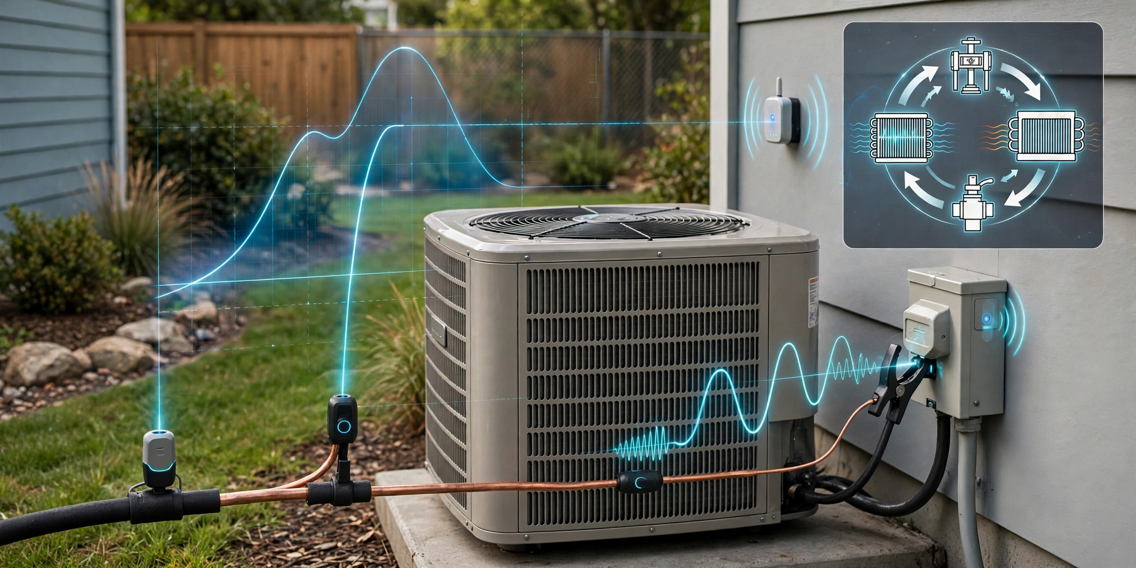
The kit contains no pressure transducer, no refrigerant sensor, and nothing that pierces, taps, or connects to the refrigerant circuit. Every sensor mounts externally and is installable by a homeowner or a general handyman:
- Two pipe-surface thermistors (10k NTC, ±0.2°C) in spring-clip housings that clamp onto the suction line (the large insulated line) and the liquid line (the small bare line) at the outdoor unit, just outside the service valves. A wrap of closed-cell foam insulates each clip from ambient air. Nominal placement tolerance is ±15 cm along the pipe.
- Two air-stream thermistors (optional but recommended) placed in the return and supply plenums at the indoor air handler, giving the evaporator air temperature split.
- One outdoor ambient thermistor mounted on the hub enclosure in shade, or read from the thermostat's outdoor sensor when available.
- One split-core current transformer (30 A or 50 A range) clamped around one leg of the outdoor unit feed inside the disconnect box, installed with the disconnect pulled. It reports true-RMS current at 1 Hz.
- One edge hub (ESP32-S3 class microcontroller with WiFi and BLE, unit cost near $6) that samples all thermistors at 0.2 Hz, reads the CT at 1 Hz, stores 90 days of per-minute features locally, and runs the full diagnostic pipeline on-device. A cloud mirror is optional; no embodiment requires continuous connectivity for the core diagnosis.
Runtime data arrives through one of two paths: a smart-thermostat API integration (ecobee, Nest, and similar expose equipment runtime) or a CT-derived runtime logger that timestamps compressor starts and stops from the current waveform. Target bill-of-materials cost for the full kit is under $30, dominated by the current transformer and the hub.
3. Acquisition and steady-state gating
Charge signatures are only meaningful at steady state. A cooling cycle enters the feature set only when the hub confirms: the compressor has run continuously for at least 10 minutes, outdoor ambient temperature has stayed within ±1.1°C (±2°F) over the preceding 20 minutes, and the indoor setpoint has not changed during the cycle. Cycles interrupted by setpoint changes, defrost (heat pumps), or low-ambient lockouts are excluded. In one embodiment the hub additionally requires the supply-air temperature to have stabilized (slope below 0.1°C per minute over 5 minutes) before sampling the air split.
Per admitted cycle the hub records: mean suction-line surface temperature, mean liquid-line surface temperature, mean outdoor ambient, mean steady-state compressor RMS current (excluding the first 90 seconds of inrush and start transient), total runtime minutes, cycle count for the day, and mean return and supply air temperatures when those sensors are present. Features are aggregated daily as ambient-binned medians (2°C bins), which removes weather as a confounder before any baseline comparison.
4. Virtual superheat and subcooling proxies
Without pressure transducers the system cannot compute true saturation temperatures, so it computes proxies anchored to the installation's own healthy behavior. During the commissioning window (Section 7), the hub fits two per-system regressions: an expected suction-line temperature as a function of outdoor ambient and return-air temperature, and an expected liquid-line temperature as a function of outdoor ambient. From these regressions the hub derives two proxies: superheat proxy, the residual of measured suction-line temperature above its expected value, and subcooling proxy, the residual of measured liquid-line temperature below its expected value. In a healthy system both residuals hover near zero across weather conditions. As charge leaks, the superheat proxy drifts positive and the subcooling proxy drifts negative, reproducing the textbook gauge-based signature without any gauge.
This proxy approach follows the virtual-sensor principle demonstrated by Li and Braun, but replaces their laboratory steady-state rig and technician calibration with per-installation self-calibration and ambient-binned residuals computed continuously at the edge. Both proxies report in temperature units (°C or °F residual), never as true superheat or subcooling, and every user-facing display labels them as estimates.
5. Compressor electrical signature
The current transformer captures the one charge indicator that moves opposite to most other faults. For each admitted cycle the hub records steady-state RMS current and normalizes it against the commissioning baseline at matched outdoor ambient (compressor current rises with ambient even in healthy systems, so raw comparisons across weather are meaningless). A sustained decline in ambient-normalized current, concurrent with a positive superheat-proxy drift, is the highest-confidence charge-loss pattern in the fusion logic. Also tracked is start-transient duration: a lengthening start transient with rising current would indicate mechanical compressor distress rather than charge loss and routes to a different diagnostic branch.
In one embodiment for inverter-driven (variable-speed) systems, where compressor current varies by design with the speed command, the hub normalizes current against the inverter's reported operating frequency (read from the equipment's communicating thermostat bus or an add-on frequency pickup) or, when no speed signal exists, restricts the current feature to cycles where the air-split and runtime features indicate full-capacity operation. Systems where no speed proxy is available carry a stated accuracy derate in the user interface.
6. Duty-cycle drift and energy waste estimation
The hub converts runtime telemetry into a daily duty-cycle series: compressor run-minutes per day normalized by cooling degree-hours computed from outdoor ambient and thermostat setpoint. This normalization separates "hot week" from "sick system." A rising normalized duty cycle means the system works longer for the same thermal load, which is exactly what capacity loss from undercharge produces. Excess run-hours multiplied by measured steady-state current and nominal voltage yield the energy-waste estimate, reported as added kilowatt-hours per month and, with the user's utility rate, added dollars per month. These are estimates with stated uncertainty bands, not metered values.
7. Adaptive per-installation baseline and commissioning
No two installations share the same charge signature: line-set length, coil sizing, metering device type, and ambient microclimate all shift the absolute temperatures. No home is ever compared against factory tables. Instead, the first 30 days after installation form a commissioning window. One prompt at install time: was the system serviced or verified cooling normally within the last 90 days? A yes answer anchors the baseline as healthy. A no answer starts the baseline in provisional mode, and the hub withholds charge-loss verdicts (reporting only raw features) until either a service visit confirms health or 60 days of stable operation establish the reference.
Baselines are living, not frozen. Each ambient bin's expected values update with an exponentially weighted moving average (90-day time constant), so gradual legitimate changes such as coil aging do not false-trigger. A service event (user taps "system serviced" in the app, or the hub detects a step improvement in all features consistent with a recharge) resets the baseline and starts a new commissioning window. Step changes larger than 3 standard deviations within 48 hours are classified as service events or sudden faults, never as gradual charge loss, which separates a recharge from a leak and a TXV failure from a slow leak.
8. Fault-decoupling logic
Four common faults mimic parts of the charge-loss signature. Decoupling runs directional tests on the fused feature set:
- Low indoor airflow (dirty filter, failing blower): suction pressure falls like charge loss, but the evaporator air temperature split rises (less air over the coil gets colder per unit) while superheat falls on fixed-orifice systems or hunts on TXV systems. Charge loss drives the air split down and superheat up. For a charge verdict, the air-split direction must agree with the charge hypothesis; when air sensors are absent, the module down-weights the verdict and names low airflow as the unexcluded alternative.
- Fouled condenser coil: head pressure rises, compressor current rises, condenser approach temperature widens. Every one of these moves opposite to charge loss. A rising-current pattern vetoes the charge-loss verdict outright and routes to a condenser-fouling branch.
- Liquid-line restriction (kinked line, clogged filter-drier): starves the evaporator like charge loss, but subcooling upstream of the restriction rises instead of falling. Here the subcooling-proxy direction decides: falling means charge loss, rising means restriction.
- Expansion-valve fault: a failed TXV produces a step change in the superheat proxy (stuck open drives it down, stuck closed drives it up within hours), while a leak produces a weeks-to-months ramp. Step-versus-ramp classification (Section 7) separates them, and a hunting oscillation detector (superheat proxy oscillating with a 2-10 minute period) specifically flags TXV hunting.
Out of the fusion module comes a charge-loss confidence score from 0 to 100 with a per-feature contribution breakdown, so a technician sees which evidence drove the verdict and which confounders were excluded. The score is a triage signal, not a measurement of remaining charge mass.
9. Graduated response
The response module maps the fused score and thermal-stress indicators to three tiers:
- Efficiency watch (score 30-59): The homeowner sees estimated capacity loss, added monthly energy cost, and a note that the pattern is consistent with early charge loss. No service urgency is asserted. First suggestion: check the air filter, since low airflow is the cheapest alternative explanation, and monitoring continues.
- Charge-loss alert (score 60-84): The system recommends a technician visit for leak detection and recharge, and generates an evidence summary the homeowner can hand to the technician: which features drifted, over what period, which confounders were excluded, and the estimated leak rate class (slow seep vs. active leak, derived from drift slope). It explicitly states that only a licensed technician with proper equipment can confirm charge and locate the leak.
- Compressor protection (score 85+, or superheat proxy above a critical threshold with raised discharge-line temperature): The system warns of active compressor damage risk from overheating and oil-return starvation, recommends prompt service, and in one embodiment offers an optional thermostat guard that raises the cooling setpoint by a user-configured amount to reduce compressor stress until service. This guard is opt-in, defaults off, and never locks out heating or emergency heat.
Every tier carries de-escalation: if features return to baseline (for example after a recharge service event), the state clears with a log entry. Alert thresholds are user-adjustable, and all defaults are documented in the open.
10. Heat pumps, inverter systems, and operating envelopes
Heat pumps reverse the refrigerant circuit in heating mode: the outdoor coil becomes the evaporator and the indoor coil the condenser, which swaps the thermodynamic roles of the two pipe sensors. Mode detection uses the thermostat's call-for-heat/cool signal or the reversing-valve solenoid current, and the hub applies a separate heating-mode baseline with its own expected-value regressions. Defrost cycles are excluded by their characteristic current and temperature transients. Cooling-mode evaluation is gated to outdoor ambient above 18°C (65°F); below that, head pressures fall for legitimate reasons and the charge signature is unreliable. Heating-mode evaluation is gated to outdoor ambient above -7°C (20°F), below which most systems run extended auxiliary heat that corrupts the duty-cycle feature. Installations outside these envelopes report features without verdicts.
11. Description of Figures
- Figure 1: Kit layout on a residential split system: clip-on pipe thermistors at the outdoor service valves, split-core CT in the disconnect, air thermistors at the air handler, and the edge hub, with wireless links shown.
- Figure 2: Charge-loss signature chart: subcooling proxy falling, superheat proxy rising, ambient-normalized compressor current falling, and normalized duty cycle rising over a 12-week simulated leak, with the commissioning window marked.
- Figure 3: Fault-decoupling decision table showing the directional feature movements for charge loss vs. low airflow, fouled condenser, liquid-line restriction, and TXV failure.
- Figure 4: Graduated response flow: efficiency watch, charge-loss alert with technician evidence summary, and compressor-protection tier with optional thermostat guard.
Claims
- A system for detecting refrigerant charge loss in a vapor-compression HVAC system, comprising: at least two pipe-surface temperature sensors clamped externally to the suction line and the liquid line with no intrusion into the refrigerant circuit; a current transformer clamped externally to the outdoor unit electrical feed; a runtime data source reporting compressor operating intervals; and an edge computing hub that fuses pipe-surface thermometry, compressor electrical current, and duty-cycle telemetry into a charge-loss confidence score, wherein the system uses no pressure transducer and no sensor in fluid communication with the refrigerant.
- The system of claim 1, further comprising a virtual superheat proxy module that computes the residual of measured suction-line surface temperature above a per-installation expected value, and a virtual subcooling proxy module that computes the residual of measured liquid-line surface temperature below a per-installation expected value, wherein a rising superheat proxy concurrent with a falling subcooling proxy indicates charge loss.
- Additionally, the system of claim 1 comprises a compressor electrical signature module that tracks ambient-normalized steady-state RMS current and treats a sustained current decline concurrent with superheat-proxy rise as a charge-loss indicator, and treats a current rise as a veto of the charge-loss verdict routing to a condenser-fouling diagnostic branch.
- In one embodiment, the system of claim 1 comprises a duty-cycle drift module that normalizes compressor run-minutes by cooling degree-hours and reports rising normalized duty cycle as capacity-loss evidence, and an energy-waste estimator that converts excess run-hours into estimated added energy cost.
- The system of claim 1, further comprising an adaptive per-installation baseline module that learns expected feature values during a commissioning window, updates them with an exponentially weighted moving average, resets on detected service events, and classifies step changes as service events or sudden faults distinct from gradual charge-loss ramps.
- Further, the system of claim 1 comprises a fault-decoupling module that separates charge loss from low indoor airflow using evaporator air temperature split direction, from liquid-line restriction using subcooling-proxy direction, and from expansion-valve failure using step-versus-ramp classification and hunting-oscillation detection.
- The system of claim 1, further comprising a graduated response module with an efficiency-watch tier reporting estimated capacity loss and energy cost, a charge-loss alert tier generating a technician evidence summary with excluded confounders and leak-rate classification, and a compressor-protection tier warning of thermal damage risk.
- The system of claim 7, wherein the compressor-protection tier includes an opt-in thermostat guard that adjusts the cooling setpoint to reduce compressor stress until service, defaulting to off and never locking out heating.
- Also, the system of claim 1 comprises a heat-pump mode module that detects heating versus cooling operation, applies separate per-mode baselines, excludes defrost transients, and gates verdicts to validated outdoor-ambient operating envelopes.
- The system of claim 1, further comprising an inverter-compensation module that normalizes compressor current against operating frequency or restricts current features to full-capacity cycles, with a stated accuracy derate when no speed proxy is available.
- A method for detecting refrigerant charge loss without pressure gauges, comprising: clamping pipe-surface temperature sensors externally to the suction and liquid lines of an installed vapor-compression system; clamping a current transformer to the outdoor unit electrical feed; collecting compressor runtime intervals; admitting only steady-state operating cycles into a feature set; computing virtual superheat and subcooling proxies as residuals against a per-installation adaptive baseline; fusing proxy drift, ambient-normalized compressor current decline, and normalized duty-cycle rise into a charge-loss confidence score with per-feature contribution breakdowns; decoupling confounder faults by directional feature tests; and issuing a graduated response proportional to the score.
- A retrofit kit for refrigerant charge-loss monitoring, comprising: two spring-clip pipe-surface thermistor assemblies with ambient-isolation foam, a split-core current transformer, an edge hub preloaded with the baseline-learning and fault-decoupling modules of claims 5 and 6, and instructions for no-intrusion installation without opening the refrigerant circuit or connecting gauges.
Implementation Notes
Install the pipe clips just outside the outdoor service valves, on clean copper, with the foam wrap snug; a clip hanging in free air reads ambient, not pipe, and the commissioning window will bake that error into the baseline. Keep the ambient thermistor shaded; direct sun on the hub enclosure invents a hot microclimate that corrupts every ambient-binned feature. Pull the disconnect before seating the current transformer, and seat it around one conductor only, not the whole cable, or the opposing currents cancel and the hub reads near zero forever.
Refrigerant type matters at the margins. R-410A, R-32, and R-454B systems all show the same directional signature, but the drift slopes differ because saturation pressure-temperature relationships differ; the per-installation baseline absorbs this automatically, which is the point of never using factory tables. For A2L mildly flammable refrigerants (R-32, R-454B), early leak awareness has a safety dimension beyond efficiency, but this system is a diagnostic, not a safety mitigation: it does not isolate refrigerant, ventilate spaces, or substitute for code-compliant leak detection where the mechanical code requires it.
Set expectations honestly. All three outputs are estimates: the proxies, the energy dollars, and the confidence score, which remains a triage signal. A technician with manifold gauges, a scale, and an electronic leak detector remains the only authority that can confirm charge state and find the leak. What this system buys is time: weeks of early warning instead of a dead compressor discovered during a heat wave, and an evidence summary that turns a vague "it doesn't cool well" service call into a targeted leak search.
Prior Art References
- Purdue virtual refrigerant charge sensor: Surface-temperature-based charge estimation without pressure gauges (Li and Braun)
- Li and Braun, ACEEE 2008: Virtual refrigerant charge sensor using low-cost noninvasive measurements
- NYSERDA visual refrigerant fault detector: ORNL prototype charge detector using differential temperature sensing
- Kim, Purdue dissertation 2014: Fault detection and diagnosis for air conditioners and heat pumps with virtual sensors
- MDPI Sensors review of virtual sensing in building systems: Virtual sensors for FDD including refrigerant charge
- US20170355246A1: Air conditioning system and method for leakage detection without pressure sensors
- WO2021050704A1: Refrigerant leak detection and mitigation via subcooling, superheat, power, and speed comparison
- US11578887B2: HVAC system leak detection using in-circuit evaporator sensors
- US5586445A: Low refrigerant charge detection using a combined pressure/temperature sensor
- US10488090B2 (Emerson): System for refrigerant charge verification (cited by number)
- US9765979B2 (Emerson): Heat-pump system with refrigerant charge diagnostics (cited by number)
- US9759465B2 (Carrier): Air conditioner self-charging and charge monitoring system (cited by number)
- 35 U.S.C. § 102: Conditions for patentability; novelty and prior art