System and Method for Estimating Air Filter Loading State in Forced-Air HVAC Systems via Blower Acoustic Signature, Motor Current, and Thermostat Telemetry Fusion
Abstract
Disclosed is a system and method for estimating the actual loading state of the air filter in a forced-air heating, ventilation, and air conditioning (HVAC) system, replacing calendar-time and equipment-runtime proxies with a direct measurement of filter pressure-drop loading. A MEMS microphone mounted on the air handler cabinet or return plenum records the blower acoustic signature during steady-state operation. A non-contact current sensor records the blower motor current waveform. Thermostat telemetry (call-for-heat and call-for-cool runtime, cycle length, duty cycle, and indoor temperature rate of change) is ingested from the installed smart thermostat. An edge hub extracts acoustic features (blade-pass tone energy and harmonics, broadband spectral centroid, tonal-to-broadband ratio), motor current features (RMS current at a fixed airflow command, current ripple, slot-harmonic content), and telemetry features (cycle lengthening, duty-cycle drift, per-cycle temperature slew rate), and compares them against a per-installation baseline anchored at each filter change to compute a filter loading index. A fault-decoupling module distinguishes filter loading from closed supply dampers, blower mechanical faults, duct blockage, and dirty evaporator coils by directional signature tests. The system issues graduated alerts (monitor, replace soon, replace now), estimates the energy and comfort cost of continued operation on a loaded filter, and contributes anonymized loading curves to fleet priors keyed by filter size and efficiency rating.
Technical Field
This invention relates to heating, ventilation, and air conditioning equipment monitoring, specifically to estimating the pressure-drop loading state of forced-air system air filters through fused acoustic, electrical, and thermostat-telemetry sensing with per-installation self-calibration.
Background
A loaded air filter is the most common correctable fault in residential HVAC. As particulate accumulates on the filter media, pressure drop across the filter rises, airflow falls, and the system pays for the same comfort with longer runtimes and higher fan energy. In cooling mode, severely restricted airflow can freeze the evaporator coil; in heating mode, it can trip high-limit switches and stress the heat exchanger. The Department of Energy advises regular filter replacement and notes that restricted airflow forces the system to work harder. The failure is mundane, which is exactly why it is expensive in aggregate: nobody's filter clogs dramatically, so everybody's filter clogs eventually.
The installed base answers this problem with timers. Google's Nest thermostats estimate system runtime from the date the homeowner last reported changing the filter and remind on a runtime-derived schedule. Ecobee thermostats offer a configurable maintenance interval (30 minutes to 8 hours of selectable reminder frequency in the user guide) anchored to a user-entered last-change date. Ecobee's Smart Thermostat Premium adds an indoor air quality monitor and reminds the homeowner to change the filter when its air quality readings degrade. Every one of these is a proxy. A filter in a home with three dogs and a nearby construction site loads in weeks; the identical filter in a low-dust home with no pets lasts many months. Runtime helps, but runtime does not know dust. The result is systematic error in both directions: premature replacement wastes money and filter media, while late replacement wastes energy, degrades comfort, and in the worst cases damages equipment.
Direct measurement exists but has not reached the home. Commercial buildings use differential pressure taps across the filter bank, a reliable method that requires penetrating the ductwork on both sides of the filter and is impractical as a retrofit in residential systems. The patent literature covers several residential approaches: US9183723B2 discloses a filter clog detection system using voltage-sensing electronics and temperature sensors; US20220404257A1 discloses a mechanical flap sensor inserted through the filter media that opens progressively as the surrounding media clogs; US10399028 discloses temperature and pressure baseline comparison for filter clogging, described primarily for cooking hoods. Mechanical whistle devices that sound when bypass flow rises are decades old and widely ignored. Each of these either penetrates the filter or the duct, adds a consumable, or measures a single channel that confounds filter loading with other airflow restrictions.
Sound-based HVAC diagnostics are an active patent area but target component faults, not filter loading. US20220381747A1 and US20220268469A1 disclose HVAC analysis engines that compare microphone recordings against audio signature libraries to diagnose faults including flame sensor faults, gas valve faults, blower faults, motor faults, and relay faults. These systems classify discrete component failures from audio alone. None estimates a continuous loading state for the filter, none fuses acoustic data with motor current and thermostat telemetry, and none self-calibrates against a per-installation clean-filter baseline captured at each filter change.
The strongest case against this system is that a timer is good enough and that acoustic signatures are too confounded to be trustworthy. Both objections carry weight. Timers are free, already deployed in every smart thermostat, and wrong only by weeks. Acoustic signatures genuinely vary with ductwork geometry, motor type, cabinet resonances, and microphone placement, and a system that compared installations against a population template would drown in that variation. The answer to the first objection is asymmetry: the cost of a timer's error is paid continuously in energy and comfort, while the cost of this system is a microphone, a current sensor, and software the thermostat already has room to run. The answer to the second is the baseline design. This system never compares an installation against a population template. It compares each installation against its own clean-filter signature, captured after every filter change, so the ductwork, the motor, and the cabinet cancel out and only the drift remains.
The gap in the art is a complete deployable system that: (a) estimates filter loading as a continuous state rather than a binary clogged-or-not verdict; (b) does so with fully non-invasive external sensing, with no duct penetration and no filter modification; (c) fuses three independent channels (acoustic, motor current, thermostat telemetry) so that no single confound can drive a false alert; (d) self-calibrates to each installation at every filter change, making the measurement relative rather than absolute; (e) decouples filter loading from the other common airflow restrictions by directional signature tests; and (f) runs the inference at the edge, keeping audio inside the home.
Detailed Description
1. Sensing architecture and mounting
The system comprises three sensing elements and one compute element, none of which penetrates ductwork or modifies the filter:
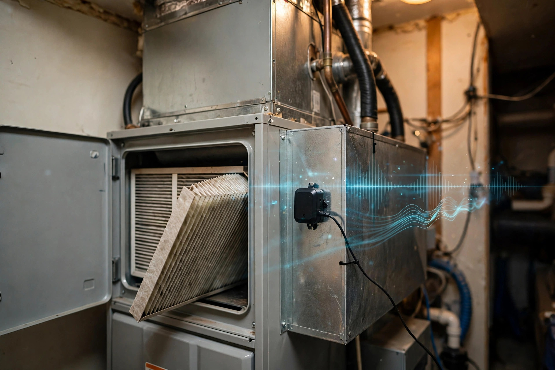
- Acoustic sensor: a MEMS microphone module (IP5x dust protection, 20 Hz to 20 kHz, 120 dB SPL handling) mounted on the exterior of the air handler cabinet or the return plenum, coupled to the sheet metal with an adhesive acoustic pad. Placement is on the return side, upstream of the blower, and away from the burner compartment on gas furnaces: combustion roar masks the blower signature during heating calls, so the cleanest measurements come from cooling and fan-only calls. A windscreen is unnecessary indoors; a 15 Hz high-pass filter rejects handling and structure-borne rumble.
- Current sensor: a split-core current transformer clamped around the blower motor hot lead inside the air handler electrical compartment, or, where the air handler exposes a communicating bus, the motor current reported by the ECM controller itself. The sensor records the current waveform at 1 kHz during blower operation, from which RMS current, ripple, and harmonic content are derived. Installation requires opening the electrical compartment but makes no wiring changes: the split core closes around the existing lead.
- Thermostat telemetry: call-for-heat and call-for-cool state, fan state, stage, indoor temperature, and setpoint, ingested from the installed smart thermostat via its local or cloud API at 1-minute resolution. No new thermostat hardware is required.
- Edge hub: a microcontroller-class device (ESP32-S3 or equivalent) that buffers sensor data during blower operation, runs the feature extraction and loading-index computation on-device, stores per-cycle features locally, and reports only the loading index and alert state outward. Target bill-of-materials cost for the kit: under $35.
In one embodiment, the acoustic sensor and hub are integrated into a single puck mounted on the return plenum, powered by a 24 VAC tap from the air handler control board (the same R and C terminals that power the thermostat), drawing under 200 mA. In another embodiment, the entire system is software-only on a smart thermostat that already contains a microphone and already receives thermostat telemetry, with the current sensor as the sole added hardware.
2. The acoustic signature of filter loading
Filter loading changes what the blower sounds like, and the physics differs by motor type. In systems with permanent split capacitor (PSC) motors, the motor runs at approximately fixed speed; as the filter loads and system static pressure rises, airflow falls, and the blower moves less air per revolution. The acoustic result is a downward shift in broadband flow noise energy and a change in the blade-pass tone relative level: the tone persists (the wheel still turns at the same speed) while the broadband whoosh of moving air diminishes, so the tonal-to-broadband ratio rises.
In systems with electronically commutated motors (ECM), the behavior inverts. Most residential ECMs run constant-airflow algorithms: as static pressure rises, the motor increases torque and RPM to hold airflow constant. The acoustic result is an upward shift: blade-pass frequency climbs, broadband energy rises with the higher wheel speed, and motor current rises with torque. Constant-torque ECM variants behave intermediately. The hub auto-detects the motor type during the commissioning window (Section 5) from the current waveform's response to a known static-pressure proxy, and thereafter applies the correct directional model. Misidentifying the motor type inverts every acoustic inference, so the auto-detection gates all loading estimates: no motor type, no index.
Feature extraction runs only on steady-state blower segments. The hub discards the first 60 seconds after blower start (ramp and duct pressurization transients) and the final 30 seconds before stop, then computes per-cycle features over the remaining steady window: blade-pass fundamental frequency and the energy in its first three harmonics; spectral centroid of the 200 to 2000 Hz band; tonal-to-broadband ratio; and band RMS. Cycles shorter than 4 minutes are excluded from the loading trend (insufficient steady window) but still counted for telemetry. Gas heating calls are tagged separately from cooling and fan-only calls because the inducer motor and combustion noise overlay the blower signature; the loading trend is computed per call type and fused with call-type weights, with cooling and fan-only calls weighted highest.
3. Motor current signature features
The current channel is the system's anchor against acoustic confounds, because it measures the motor's effort directly. For constant-airflow ECMs, the hub tracks RMS current at each commanded airflow stage against the clean-filter baseline for that stage: a rising current trend at fixed stage is the most direct electrical signature of rising static pressure, and therefore of filter loading. For PSC motors, RMS current moves little with loading, so the hub instead tracks current ripple and slot-harmonic content, which shift as the motor's operating point moves along its torque curve.
Current is also the primary input to the fault-decoupling module (Section 6). A blower mechanical fault (bearing wear, unbalanced wheel) raises current ripple and adds vibration-coupled modulation sidebands around the slot harmonics without the slow, monotonic static-pressure signature of filter loading. An electrical fault (failing capacitor on a PSC motor, demagnetization on an ECM) changes the current waveform shape abruptly rather than drifting over weeks. The current channel therefore both corroborates the acoustic loading estimate and vetoes it when the signature shape indicates the motor itself is the problem.
4. Thermostat telemetry fusion
The thermostat already observes the consequences of restricted airflow, and the hub converts those observations into corroborating features. As the filter loads and delivered airflow falls, the system must run longer to move the same heat: cycle length extends for the same indoor-to-setpoint gap, duty cycle rises across comparable weather, and the per-cycle indoor temperature slew rate (degrees per minute during a call) declines. The hub normalizes these against outdoor temperature, using either a local weather feed or the thermostat's own outdoor sensor, because a heat wave lengthens cycles for reasons that have nothing to do with the filter.
Telemetry is the slowest channel: it needs days of cycles to separate a trend from weather noise, while the acoustic and current channels respond within a single steady-state cycle. The fusion weights reflect this. The loading index is computed as a weighted combination with acoustic and current features dominant on short timescales and telemetry acting as a slow confirmatory drift term. When all three channels agree, confidence is high; when the acoustic channel drifts while current and telemetry hold steady, the system suspects an acoustic confound (a new noise source near the microphone, a loosened mounting pad) and withholds the alert pending corroboration.
5. Per-installation baseline and filter-change anchoring
No two installations share an acoustic signature, and the system never assumes otherwise. After installation, or after every filter change, the hub captures a clean-filter baseline: the median of each feature across the first 20 qualifying steady-state cycles (or 7 days, whichever comes first), computed separately per call type and per blower stage. All subsequent loading estimates are expressed as normalized drift from this baseline, so cabinet resonances, duct geometry, and microphone placement cancel out.
Filter changes are detected, not just declared. A fresh filter produces a characteristic snap-back: acoustic and current features step back toward (and usually slightly past, since the old baseline was captured on a partially loaded filter) the previous baseline within one or two cycles. When the hub observes a snap-back exceeding three standard deviations of the recent feature noise, it prompts the homeowner to confirm a filter change and, on confirmation, re-anchors the baseline. If the homeowner changes the filter without the app noticing (no snap-back detected, for example because the old filter was nearly clean), a manual "filter changed" input re-anchors unconditionally. Until a baseline exists, the system reports raw features only and issues no loading verdicts: no baseline, no index.
Air density compensation is applied to acoustic features using indoor temperature and an assumed or measured barometric pressure, because cold dense air shifts flow-noise spectra independently of loading. The compensation is small indoors but prevents seasonal drift from masquerading as filter loading in unconditioned spaces.
6. Fault decoupling by directional signature tests
Several common faults restrict airflow or change the blower signature, and a loading estimate that cannot separate them will cry wolf. The decoupling module runs directional tests on the fused feature set:
- Filter loading: slow monotonic drift over weeks in acoustic and current features, corroborated by lengthening cycles and rising duty cycle in telemetry, with no step changes and no new tonal components. The signature evolves gradually because dust accumulates gradually.
- Closed or blocked supply dampers/registers: step change in acoustic features (a register slammed shut changes the system curve in one cycle, not over weeks), often with a new whistling tonal component at the restricted register and a current step rather than a drift. The module checks for step timing: drift means filter, step means damper.
- Blower mechanical fault: rising current ripple, new vibration-coupled sidebands, or a new tonal component at wheel rotational frequency, with acoustic drift that does not match the loading direction for the known motor type. Current vetoes the loading estimate and the system reports a blower fault instead.
- Duct blockage or collapse: large step change in static-pressure proxies, sometimes with flapping or drumming acoustic components from a loose duct section. Treated like a damper step: sudden, not gradual.
- Dirty evaporator coil: the closest mimic, since a fouled coil also raises static pressure gradually. Disambiguation uses placement and call-type weighting: the microphone sits on the return side, where filter loading dominates the acoustic change, and coil fouling additionally degrades cooling capacity per unit runtime (supply air fails to reach expected temperature depression), a telemetry signature that filter loading produces only weakly. When the two cannot be separated, the alert names both and recommends checking the filter first, since it is the user-serviceable one.
- Filter rack bypass: air leaking around the filter frame rather than through it. Heavy bypass mutes the loading signature (pressure drop rises less than the dust load implies) and the system reports reduced confidence rather than a false clean bill of health.
7. Filter loading index and graduated response
The fused features map to a filter loading index from 0 (clean-filter baseline) to 100 (replacement threshold), where 100 corresponds to the feature drift associated with the filter manufacturer's rated final pressure drop for the installed filter size and MERV rating (per ASHRAE Standard 52.2 rating conventions). The mapping is calibrated per installation: the index reaches 100 when the observed drift equals the drift measured across a full loading cycle on that installation, or, before a full cycle has been observed, when drift reaches the fleet-prior expectation for the filter type (Section 8).
The response module maps the index to three tiers. Monitor (index 0-60): the loading trend is displayed with a projected weeks-to-replacement based on the drift rate. Replace soon (index 60-85): the homeowner is notified with the projected date and the estimated energy cost of delaying. Replace now (index above 85, or any decoupling veto cleared with index above 75): the alert states the filter is loaded, names the confidence level, and lists the confounds that were checked and excluded. All thresholds are user-adjustable, and every alert links to the underlying feature trends so a skeptical homeowner can see the drift rather than taking the system's word for it.
Illustrative worked example (not a measured result): consider a 3-ton system with a 20x25x1 MERV 11 filter and a constant-airflow ECM blower. Suppose the clean-filter baseline shows 4.1 A RMS at the cooling airflow stage with a blade-pass tone at 118 Hz, and that after 10 weeks the current has drifted to 4.6 A with the tone at 131 Hz while cooling cycles have lengthened 12 percent against comparable weather. The hub would map this drift to an index in the replace-soon band and project roughly 3 to 5 weeks to the replace-now threshold at the observed drift rate. These numbers are illustrative of the computation, not measurements from any prototype.
8. Fleet priors and seasonal confounds
In one embodiment, installations contribute anonymized per-cycle features (never audio recordings, never identity or location) to a fleet dataset keyed by filter nominal size, MERV rating, motor type, and system tonnage. Fleet priors seed the index calibration for new installations before they have observed a full loading cycle, and they shorten the provisional period: a new 20x25x4 MERV 13 installation on a constant-airflow ECM starts with the fleet's loading-curve shape for that configuration and refines toward its own signature over the first filter life. Contribution is opt-in, and the base system's estimates never require fleet connectivity.
Seasonal confounds are handled explicitly. Wildfire smoke events, nearby construction, and pollen season load filters faster than the drift-rate projector expects; the system detects accelerated drift, shortens the projection, and labels the acceleration rather than silently moving the date. Conversely, shoulder seasons with little blower runtime produce few qualifying cycles; the hub widens the index uncertainty band and says so, instead of projecting confidently from sparse data. A filter that loads during a smoke event and then sits through a mild spring is still loaded: the index does not decay with disuse.
9. Edge inference and privacy
All audio processing happens on the hub. Raw audio is buffered in a rolling 10-minute window, features are extracted, and the audio is discarded; no audio is stored long-term and no audio leaves the home in any embodiment. Only per-cycle feature vectors and the loading index are reported outward. The microphone's placement on the air handler means it primarily hears the blower, but it can incidentally capture household sound during fan operation; the on-device-only processing and no-storage design exist to make that incidental capture unrecoverable. The privacy properties are architectural, not policy-based: there is no cloud audio pipeline to opt out of because there is no cloud audio pipeline.
10. Description of Figures
- Figure 1: System layout on a residential forced-air system: MEMS microphone module on the return plenum, split-core current transformer on the blower motor lead, edge hub, and the installed smart thermostat, with data flows between them.
- Figure 2: Acoustic feature drift illustration for a constant-airflow ECM system: blade-pass tone frequency and RMS current rising monotonically across a filter loading cycle, with the clean-filter baseline band marked.
- Figure 3: Contrasting PSC behavior: tonal-to-broadband ratio rising as broadband flow noise diminishes with falling airflow at fixed motor speed.
- Figure 4: Fault-decoupling decision table showing directional feature movements for filter loading, closed dampers, blower mechanical fault, duct blockage, dirty evaporator coil, and filter rack bypass across the acoustic, current, and telemetry feature sets.
- Figure 5: Filter-change snap-back: feature step response on filter replacement and baseline re-anchoring, with the provisional baseline window marked.
Claims
- A system for estimating air filter loading state in a forced-air HVAC system, comprising: a microphone mounted externally to the air handler cabinet or return plenum that records a blower acoustic signature during blower operation; a non-contact current sensor that records a blower motor current waveform; a thermostat telemetry interface that ingests call-for-heat state, call-for-cool state, fan state, indoor temperature, and setpoint from an installed thermostat; and an edge computing hub that extracts acoustic features, motor current features, and telemetry features, compares the features against a per-installation baseline anchored at a clean-filter state, and computes a filter loading index representing pressure-drop loading of the air filter, wherein no sensor penetrates ductwork and no sensor modifies the air filter.
- The system of claim 1, wherein the acoustic features comprise blade-pass tone frequency and harmonic energy, broadband spectral centroid, and tonal-to-broadband ratio, extracted only from steady-state blower segments with ramp transients excluded, and computed separately per call type with cooling and fan-only calls weighted above gas heating calls.
- The system of claim 1, further comprising a motor-type detection module that classifies the blower motor as constant-airflow ECM, constant-torque ECM, or PSC from the current waveform's response during a commissioning window, and applies the corresponding directional loading model, wherein constant-airflow ECM loading is indicated by rising current and rising blade-pass frequency at fixed airflow command, and PSC loading is indicated by rising tonal-to-broadband ratio at approximately fixed motor speed, and wherein no loading index is issued until the motor type is classified.
- The system of claim 1, wherein the telemetry features comprise cycle length normalized against indoor-to-setpoint gap, duty cycle normalized against outdoor temperature, and per-cycle indoor temperature slew rate, fused as a slow confirmatory drift term weighted below the acoustic and current features on short timescales.
- The system of claim 1, further comprising a fault-decoupling module that distinguishes filter loading from closed supply dampers, blower mechanical faults, duct blockage, dirty evaporator coils, and filter rack bypass by directional signature tests, wherein gradual monotonic drift in the acoustic, current, and telemetry features indicates filter loading, step changes indicate dampers or duct events, current ripple with new tonal sidebands indicates blower mechanical fault and vetoes the loading estimate, and reduced signature response with bypass-consistent features reports reduced confidence rather than a clean-filter verdict.
- The system of claim 1, further comprising a filter-change detection module that identifies a snap-back of the acoustic and motor current features exceeding three standard deviations of recent feature noise within two blower cycles, prompts for homeowner confirmation, and re-anchors the per-installation baseline on confirmation, and that accepts a manual filter-changed input to re-anchor unconditionally.
- The system of claim 1, further comprising a graduated response module with a monitor tier displaying the loading trend and projected weeks to replacement, a replace-soon tier with a projected replacement date and an estimated energy cost of delay, and a replace-now tier naming the confidence level and the confounds checked and excluded, with user-adjustable thresholds and feature trends visible to the homeowner.
- The system of claim 1, wherein the edge hub processes all audio on-device within a rolling buffer, discards raw audio after feature extraction, stores no long-term audio, and transmits only per-cycle feature vectors and the loading index outward.
- The system of claim 1, further comprising a fleet-prior module that seeds index calibration for new installations from opt-in anonymized per-cycle features keyed by filter nominal size, efficiency rating, motor type, and system tonnage, and that labels accelerated drift from wildfire smoke, construction, or pollen-season events rather than silently adjusting projections.
- A method for estimating air filter loading state in a forced-air HVAC system, comprising: mounting a microphone externally to the air handler cabinet or return plenum and a non-contact current sensor on the blower motor lead, without penetrating ductwork or modifying the air filter; recording blower acoustic signatures and motor current waveforms during steady-state blower operation across a commissioning window after a filter change to establish a per-installation clean-filter baseline; classifying the blower motor type from the current waveform; extracting acoustic, current, and thermostat-telemetry features from subsequent blower cycles; computing normalized drift of the features from the baseline; decoupling filter loading from damper, blower, duct, coil, and bypass confounds by directional signature tests; and issuing a graduated filter replacement alert based on a filter loading index derived from the decoupled drift.
- A retrofit kit for forced-air HVAC filter loading estimation, comprising: an adhesive-mount MEMS microphone module for the return plenum or air handler cabinet exterior; a split-core current transformer for the blower motor lead; an edge hub preloaded with the steady-state segmentation, motor-type detection, feature extraction, baseline anchoring, fault-decoupling, and graduated-response modules of claims 1 through 9; and instructions for no-penetration installation requiring no ductwork modification and no filter modification.
Implementation Notes
Mount the microphone on the return side, not the supply side. The filter sits in the return path, and its loading signature is strongest where the pressure drop actually occurs. On upflow gas furnaces this means the blower compartment or the return plenum, kept clear of the burner compartment: combustion roar during heating calls will dominate the recording and the hub will down-weight those cycles anyway, so placement that favors clean cooling and fan-only measurements pays off all year.
Expect the filter rack to leak. Residential filter racks routinely bypass a meaningful fraction of return air around the filter frame, and heavy bypass mutes the loading signature because the system static pressure rises less than the dust load implies. The system reports reduced confidence in this condition rather than a false clean verdict. Sealing the rack with foam tape is a five-minute improvement that helps both the measurement and the filtration.
Do not rely on whistling. Some loaded filters whistle as bypass flow through the remaining open media accelerates, and some never do; the whistle is a curiosity, not a signal. The loading estimate uses the full feature set with the whistle absent, and treats a whistle as corroboration at most.
A torn or collapsed filter can read as clean. The acoustic and current signatures respond to pressure drop, and a filter with damaged media passes air freely. This system estimates loading, not filtration integrity, and a visual inspection still has a job. Say this plainly in the product documentation: the sensor measures how hard the filter is working, not whether the filter is intact.
Multi-filter returns and filter grilles need one baseline per configuration, not per filter. If the system has two return grilles with filters, a change at one grille produces a partial snap-back; the hub attributes the step proportionally and re-anchors the combined baseline. Media cabinets (4 to 5 inch deep filters) load over 6 to 12 months; the drift is slow enough that the exponentially weighted baseline updater must use a long time constant or it will absorb the loading trend into the baseline and report a perpetually clean filter. Set the baseline time constant longer than the longest expected filter life for the installed filter type.
Set expectations about what the number means. The loading index tracks pressure-drop loading, which correlates with energy waste and comfort degradation but is not itself a health or air-quality measurement. A MERV 13 filter at index 80 is still filtering; it is just making the blower work harder to pull air through. The energy-cost-of-delay estimate is an estimate, and the documentation should show its inputs (drift rate, local electricity rate, duty cycle) rather than presenting a single authoritative dollar figure.
What this system buys is the replacement of a timer with a measurement. The timer's error is systematic: it cannot know about the dogs, the construction site, or the smoke season, so it is wrong in the same direction for the same homes, year after year. A measurement anchored to each installation's own clean-filter signature inherits none of that error. The homeowner who gets a replace-soon alert in week 9 of a smoke season instead of a calendar reminder in month 6 changes the filter when it is actually loaded, and the blower stops paying the pressure-drop tax weeks earlier.
Prior Art References
- Google Nest filter reminders: Runtime-estimated filter reminders anchored to user-entered last-change date
- Ecobee3 user guide: Configurable furnace filter maintenance interval with user-set last-change date
- Ecobee Smart Thermostat Premium: Built-in air quality monitor with filter-change reminders tied to air quality readings
- US9183723B2: Filter clog detection and notification system (voltage-sensing electronics, temperature sensors)
- US20220404257A1: Airflow filter sensor (mechanical flap inserted through filter media)
- US10399028: Filter clogging monitoring systems and methods (temperature/pressure baseline comparison)
- US20220381747A1: Sound-based prognostics for a combustion air inducer (HVAC audio signature library)
- US20220268469A1: Sound-based HVAC system diagnostics (audio signatures for component fault types)
- ASHRAE Standard 52.2: Method of Testing General Ventilation Air-Cleaning Devices for Removal Efficiency by Particle Size (MERV rating conventions referenced for index calibration)
- 35 U.S.C. § 102: Conditions for patentability; novelty and prior art