System and Method for Estimating Frost Accumulation and Controlling Demand-Based Defrost in Air-Source Heat Pumps Using Outdoor Fan Current, Acoustic, and Refrigerant Pressure Fusion
Abstract
Disclosed is a system and method that estimates how much frost has accumulated on the outdoor coil of an air-source heat pump, and uses that estimate to run defrost only when frost is present and to end defrost when the coil is clear. In heating mode the outdoor coil runs colder than the air around it, so moisture in the air freezes onto the fins. That frost insulates the coil and chokes airflow, which cuts heating capacity and efficiency, and the standard cure is a defrost cycle that reverses the refrigerant flow, stops delivering heat to the house, and often fires auxiliary electric heat. Today's heat pumps decide when to defrost with a timer, a coil temperature threshold, or at best a humidity input, and a field study found that 63 percent of the defrost cycles run by time and coil temperature control were unnecessary. This disclosure replaces the timer with measurement.
It reads frost from three measured channels that already exist on or near the unit: outdoor fan current, outdoor fan acoustics, and refrigerant suction and discharge pressure with coil temperature. Those channels are fused into a frost index on a 0 to 1 scale, learned against a clean-coil baseline for the specific unit, with a forecast of frost growth rate from outdoor humidity and dew point. Defrost starts when the index crosses a threshold with at least two measured channels in agreement, apart from the 4-hour maximum-interval guard in section 8, and it ends when two consecutive fan test pulses during defrost show the fan power, adjusted for air density, and the turbulence band back within 5 percent and 10 percent of their clean-coil values respectively (the termination bands defined in section 8), which is the coil showing itself clear. Every verdict is corrected for the mimics that fake it: rain and snow on the coil, wind gusts, low refrigerant charge, a dirty coil, fan bearing wear, and auxiliary heat operation.
Output is a defrost decision made on evidence, a frost index with its supporting channels shown, a forecast of when the next defrost will be needed, and a termination that stops the reversed cycle the moment the coil is clear, so a heat pump stops paying the energy cost of defrosting a clean coil and stops running defrost longer than the frost requires.
Field of the Invention
This invention relates to control of air-source heat pumps, specifically to estimating frost accumulation on the outdoor evaporator coil from outdoor fan current, fan acoustics, and refrigerant pressure and temperature, with per-unit baseline learning and confound separation, for demand-based defrost initiation, measurement-based defrost termination, and frost growth forecasting in residential and light commercial heating.
Background
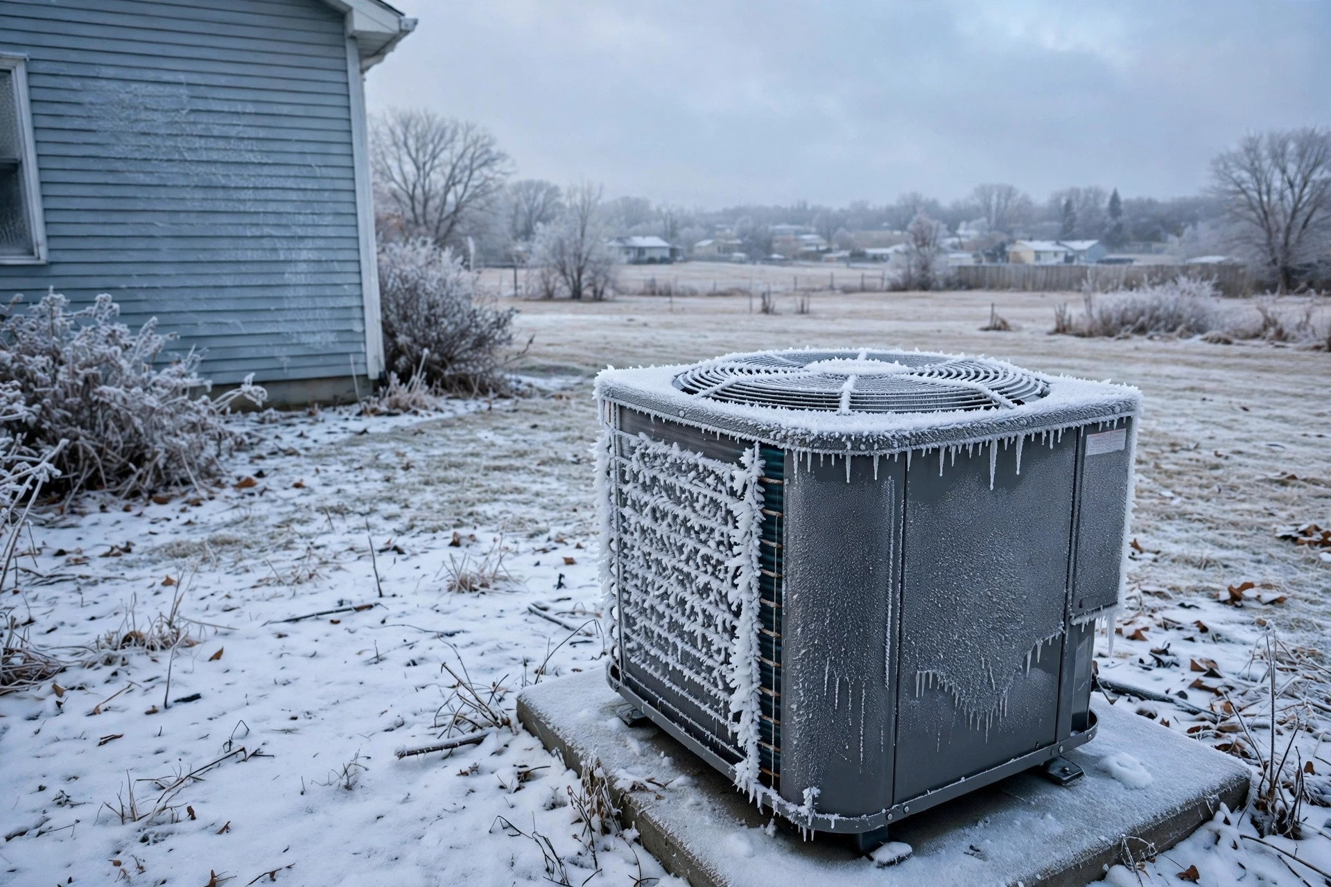
An air-source heat pump heats a house by moving heat from cold outdoor air into the house, which requires the outdoor coil to run colder than the air passing over it. In heating mode the outdoor coil is the evaporator, and its surface typically sits 8 to 12 degrees Celsius below outdoor air temperature. When outdoor air is near or below freezing and carries moisture, that moisture condenses on the cold fins and freezes. Frost builds up over tens of minutes to a few hours, and it hurts in two ways at once. It insulates the coil, because frost conducts heat at roughly 0.2 watts per meter-kelvin against about 200 for the aluminum fins it coats, so heat transfer from the air to the refrigerant falls. And it blocks airflow, because the frost narrows the gaps between fins and raises the air-side pressure drop, so less air reaches the coil at all. A 2026 field study of 22 pre-commercial cold-climate units, published in Energy Efficiency, puts the combined penalty at a 30 to 60 percent reduction in heating capacity and coefficient of performance (COP) under frosted conditions, summarizing work by Wang and colleagues from 2020 in its literature review. The cure is a defrost cycle: the four-way reversing valve flips, the outdoor coil becomes the condenser, hot refrigerant melts the frost, and the indoor coil goes cold, blowing cool air into the house while auxiliary electric heat strips (electric resistance heaters), at 5 to 15 kilowatts, often fire to cover the gap.
Defrost is expensive, and it is paid for twice. First in direct energy: the reversing valve flips, sending hot refrigerant to the outdoor coil to melt frost instead of heating the house, and the auxiliary heat adds its own draw. A multi-year field measurement at Oak Ridge National Laboratory found defrosting responsible for 10.1 percent and frosting itself for another 3.6 percent of total seasonal heating energy consumption, with both shares measured exclusive of supplemental electric resistance-heater energy. An energetic analysis of defrosting systems puts the defrost share as high as 14 percent of the heating season. Second in lost capacity: no heat is delivered indoors during a cycle that typically lasts 5 to 15 minutes and repeats every 30 to 90 minutes in freezing weather, so at the frequent end of that range, 15 minutes of defrost after 30 minutes of heating, defrost occupies a third of clock time, 20 minutes of each hour. A heat pump in a cold damp climate can lose 3 to 12 percent of its winter heating energy to defrost, and the spread between a well-sited unit with modern control and a poorly sited unit with old control is the difference between 3 to 5 percent and 8 to 12 percent of winter heating energy, a gap that compounds over a 15-year asset life.
Current practice decides when to defrost with far less information than the unit already has. The common control is a timer plus a coil temperature threshold: after 30, 60, or 90 minutes of heating, if the coil is cold enough, defrost runs. Some premium units add outdoor humidity as an input, which the same literature review reports improves COP by 4.6 percent. But the timer cannot tell a dry cold night from a damp one, and the coil temperature cannot tell frost from a cold snap. As summarized in the literature review of the same field study, a field study by Zhu and colleagues in 2015 found that a unit controlling defrost from heating time and outdoor coil temperature ran 63 percent of its defrost cycles when defrosting was not necessary. The same literature review also reports a laboratory study by Klingebiel and colleagues in 2025 that found this time-and-temperature strategy can cost 16 percent in efficiency against an optimal control, and that demand-based strategies using evaporator temperatures, static pressure differential across the evaporator, or COP and capacity change can cut that loss from 16 percent down to 7 percent.
Existing art comes closer than the market does, and the gap this disclosure fills is specific. US4843838A controls defrost initiation and termination with a dual pressure switch on the outdoor coil plus a clock timer, but it is a single pressure channel gated by a timer, with no fan measurement, no acoustic measurement, no baseline learning, and no forecast. US4439995A provides frost monitoring for a self-contained unit, but its control interrupts heating on a frost sensor alone, with no fusion of independent channels and no measurement of when the coil is clear.
EP4071417B1 reads flag bits for several defrosting parameters, including fan input power checked against a preset ambient-temperature curve measured on a clean coil, and adjusts the defrost sequence from the compressor discharge and suction pressure difference, but it works from threshold flags rather than a fused index, its fan-input-power curve is a preset lab-measured curve rather than a per-unit learned baseline for that parameter (although it does carry forward the heat-production power recorded after one defrost as the preset for the next), it uses no acoustic channel, and it does not forecast frost growth or terminate on measured return of the fan and acoustic signatures to their clean baseline (it does terminate on fin-coil temperature crossing a preset threshold). Per-unit learned baselines are themselves known: Trane demand-defrost controls learn a clean-coil Delta-T on a first learning defrost and initiate at about 1.9 to 2.0 times that clean-coil value, and Trane's defrost-learning patent adjusts the clear-coil and initiate Delta-T lines from operating experience (US20160238301A1). US20240011655A1 improves the defrost itself, varying indoor blower speed from suction line pressure to reduce the cold blow and avoid a low-pressure lockout, but it manages a defrost already in progress rather than deciding whether one is needed.
No cited control provides all of these together in the combination claimed here: fuse outdoor fan current with fan acoustics and refrigerant pressure into a learned frost index, forecast frost growth from dew point, require two-channel agreement before defrosting, and terminate defrost on measured return of the fan and acoustic signatures to their clean baseline. The pairs are not new: EP4071417B1 already combines fan input power with suction pressure, US20190003760A1 already uses fan power alone, US5051645A already uses acoustic sensing alone by a contact sensor, and US10488098B2 already uses airborne acoustic sensing alone by an active sound source and a microphone. The novelty claimed is the triple fusion with the airborne acoustic channel, per-unit learned fingerprints for all three channels together with renormalized fusion, and the test-pulse termination, not any one channel and not learned baselining alone. That is what this disclosure provides.
Detailed Description
1. Inputs and System Architecture
Three embodiments cover the range from a factory control board to a clamp-on retrofit. In the preferred embodiment, the heat pump controller reads sensors already present on modern variable-speed units: outdoor fan motor current and speed, a MEMS (micro-electromechanical systems) microphone mounted in, on, or adjacent to the outdoor unit cabinet and acoustically coupled to the outdoor fan, suction and discharge pressure transducers, coil temperature measured at the coil surface, a suction-line temperature sensor at the evaporator outlet from which superheat (how far the refrigerant vapor has warmed above its boiling temperature) is computed with the saturated suction temperature, outdoor air temperature, relative humidity, and barometric pressure, and compressor speed and current. In a second embodiment, a retrofit hub adds a clamp-on current sensor on the outdoor fan lead, a weatherproof microphone clipped to the unit cabinet, and a connection to the thermostat for auxiliary heat status, with outdoor temperature and humidity taken from a local weather feed where no sensor exists, and makes no connection to the refrigerant circuit. In a third embodiment, a fleet aggregator for a heat pump maker or a utility collects aggregated frost curves per unit model across many homes. Those curves set model-specific defrost thresholds, spot a batch of units whose coils frost faster than their class, and schedule defrosts away from grid peak where the utility offers a demand-response signal. In all embodiments only derived features leave the home: fan current summaries, acoustic summaries, pressure and temperature timing, and humidity, never audio recordings of the yard.
Every heating cycle is tagged with the variables that move frost. Outdoor air temperature, relative humidity and dew point, coil temperature, compressor speed, fan speed, heating run time since the last verified-clear state, and auxiliary heat status, tagged on every cycle. A cycle without a humidity tag is used for the measured channels only, and the forecast in section 6 is not computed.
2. Baseline Learning
Before any verdict, the system learns the unit's clean-coil behavior. The baseline is taken over the first two stable weeks of the heating season after a verified-clear coil, where a coil is verified clear when it has just completed a defrost that terminated by measurement under section 8, or when it is visually confirmed clear at commissioning or after cleaning, and where stable weeks means two weeks of heating operation with no defrost flagged under section 8 as a possible failed defrost, failed reversing valve, or sensor fault and with outdoor temperature spanning at least three values at least 2 degrees Celsius apart and humidity spanning at least three values at least 10 percentage points apart.
The baseline stores four heating fingerprints, the stored clean-coil values for each channel, as functions of outdoor temperature, humidity class, compressor speed, and fan speed: outdoor fan power, the acoustic spectrum of the outdoor fan, suction pressure expressed as saturated suction temperature (the boiling temperature of the refrigerant at that suction pressure), and superheat at the evaporator outlet (how far the refrigerant vapor has warmed above its boiling temperature by the time it leaves the coil). Humidity class means one of three relative-humidity bands: below 50 percent, 50 to 80 percent, and above 80 percent. Matched conditions means baseline and current values in the same humidity class and within 2 degrees Celsius of outdoor temperature, the same compressor speed setting where compressor speed is reported, and the same fan speed setting where fan speed is reported. Two more fingerprints, for the turbulence band at the test speed and, where fan current is present, for fan power at the test speed, are learned separately during defrost, from the same verified-clear coil at the fixed test speed, so a test pulse has its own baselines to compare against.
The test-speed fingerprints are first learned from the final two test pulses of the first defrost following a coil verified clear by visual confirmation at commissioning or after cleaning, taken as the clear-coil reference on the basis that that defrost has run to the fixed maximum duration of section 8 rather than terminating by measurement; measurement-based termination applies only once the test-speed fingerprints exist. The test-speed fingerprints are refreshed only from a later defrost that ends on two consecutive clear pulses. The four fingerprints feed three channels: fan current and acoustics are separate channels, and the two refrigerant fingerprints, saturated suction temperature and superheat, are sub-measurements of one pressure channel, which takes the greater of the two normalized drifts.
Frost is defined strictly as drift away from this baseline at matched conditions, never as an absolute number, because two healthy units of different size and fan design differ more from each other than a clean coil differs from a frosted one of the same model. A change of outdoor unit re-baselines everything. A change of fan motor re-baselines the fan and acoustic channels only, because the refrigerant channels do not move with the fan.
The baseline is refreshed after every defrost that terminates by measurement, as described in section 8, because a verified-clear coil is a fresh clean reference. Baselines are kept per season, since a coil that is clean in November and dirty in February is not the same coil, and the slow drift of a dirty coil is tracked separately from the fast drift of frost, as described in section 9.
3. The Outdoor Fan Current Channel
Fan current is the channel that feels the coil choking. As frost narrows the fin gaps, the air-side pressure drop across the coil (the resistance the air meets passing through the fin gaps) rises and the fan's operating point (the combination of airflow and pressure at which the fan is running) moves. The direction of the current change depends on the fan type, and the system learns the direction at commissioning rather than assuming one. On a fixed-speed axial (propeller) fan, the type fitted to most outdoor units, airflow falls as resistance rises and motor power rises with it, because a propeller fan loads more as flow is throttled; on a fixed-speed centrifugal fan, motor power falls modestly as airflow falls. On a constant-airflow electronically commutated fan (a brushless motor whose speed is set by electronics rather than by mains frequency), the controller raises speed to hold airflow against the rising resistance, and motor power rises. The rise on a propeller fan and the fall on a centrifugal fan are both frost signatures, opposite in direction depending on fan type, and both are invisible to a timer.
Implementation is deliberately modest. Fan power is sampled at 1 hertz and summarized as 5-minute medians, because wind gusts move instantaneous fan current and a median over 5 minutes removes them. The feature is the deviation of median fan power from the clean baseline at matched outdoor temperature, humidity class, compressor speed, and fan speed setting, expressed as a percentage. A sustained deviation of 10 percent or more in the learned direction, held over at least 15 minutes, is a frost vote, not a verdict. US20190003760A1 already teaches initiating defrost when fan power at a fixed speed falls about 10 percent below its unblocked value, a teaching that holds for a fixed-speed centrifugal fan; this disclosure differs in that it learns the direction at commissioning, so a constant-airflow fan whose power rises against frost also votes, it uses 5-minute medians and a 15-minute sustain requirement, and a fan vote alone never triggers defrost. Whether two such votes trigger a defrost is defined in section 7. One gusty 5 minutes is weather. Fifteen minutes of drift is frost.
4. The Acoustic Channel
Acoustics is the channel that hears the coil choking. No cited defrost control is known to use passive airborne fan acoustics, a cabinet microphone measuring blade-pass tone drift and turbulence-band rise, as a frost channel. US5051645A teaches acoustic frost sensing by a different means, a surface-acoustic-wave sensor in contact with an evaporator fin that detects the phase change on the fin itself, not the sound of the fan moving air through a frosted coil. US10488098B2 also teaches airborne acoustic frost sensing, but by a different means again: an active sound source transmitted toward the evaporator and a microphone receiving the reflected or transmitted sound, not the passive sound of the fan itself, with no fan-current or pressure channel and no blade-pass tone or turbulence-band feature. A clean outdoor fan has a stable acoustic signature: a blade-pass tone at fan speed times blade count divided by 60, plus a broadband turbulence floor from air moving through the coil. Frost distorts that signature in three measurable ways. First, the broadband turbulence energy in the 500 hertz to 4 kilohertz band rises, because air forced through narrowed fin gaps moves faster through the remaining openings and sheds stronger vortices. Second, the blade-pass tone shifts and broadens, because the fan works against higher resistance and its speed wanders under load. Third, the coil itself changes acoustically, because a frost layer alters the acoustic impedance of the fin pack (how much it resists and reflects sound), absorbing and reflecting sound differently than bare aluminum.
The acoustic implementation is equally restrained. The microphone samples at 16 kilohertz, audio is processed in 1 second frames with 50 percent overlap, and each frame yields three features: energy at the blade-pass tone and its first two harmonics, multiples of the blade-pass tone frequency, RMS (root-mean-square, a measure of average signal strength) energy in the 500 hertz to 4 kilohertz turbulence band, and RMS energy below 200 hertz for low-frequency loading, the rise in low-frequency energy as the fan works harder against the frosted coil, measured net of the blade-pass tone and its harmonics. The low-frequency loading feature is diagnostic only; it casts no vote and enters no channel value. Features are summarized per heating cycle as the time course of each band and the drift of the blade-pass tone from its clean baseline. No absolute decibel calibration is needed, because the features are ratios and shapes, not levels, and the baseline is taken on the same microphone in the same cabinet. A cycle recorded during heavy rain is flagged by its broadband noise floor and the acoustic channel abstains from casting a frost vote for that cycle and its channel value is excluded from the frost index for that cycle, with the weights of the remaining measured channels renormalized proportionally to sum to 0.90 for that cycle, where heavy rain means the broadband noise floor, measured as energy per frequency bin, is at least 50 percent above its clean baseline value, because rain masks the acoustic signature and wets the coil so the acoustic channel cannot be trusted on that cycle. The vote is also withheld and its channel value excluded when the broadband noise floor is so high that the blade-pass tone cannot be resolved at all, meaning the blade-pass tone energy is less than twice the broadband noise energy in the same frequency bin as the blade-pass tone in the same frame.
5. The Refrigerant Pressure and Temperature Channel
Refrigerant pressure shows the thermodynamic cost of frost. As frost insulates the coil, the refrigerant must run colder to pull the same heat from the air, so the saturated suction temperature falls and suction pressure with it. Superheat at the evaporator outlet rises, because the frosted portion of the coil contributes less boiling and the vapor has further to travel before it leaves the coil. Discharge pressure moves less, so the suction-to-discharge pressure differential widens. Discharge pressure is recorded as a diagnostic; no vote or channel value depends on it. The system records suction pressure as saturated suction temperature, discharge pressure, superheat, and coil temperature at 1 minute intervals, and compares each against the clean baseline at matched conditions as defined in section 2.
A fall of 3 degrees Celsius or more in saturated suction temperature at matched conditions as defined in section 2, sustained over at least 15 minutes, is a frost vote. A rise of 3 degrees Celsius or more in superheat at matched conditions as defined in section 2, sustained over at least 15 minutes, is an alternative pressure vote, and the pressure channel value is the greater of the two normalized drifts. That channel moves slowest and recovers slowest, which makes it a poor trigger on its own and a good confirmer: when the fan and acoustic channels say frost and the suction temperature has fallen with them, the three channels are describing the same physical event from three independent directions.
6. Frost Formation Rate Forecast
Forecasting is the feature that turns a frost measurement into a schedule. Frost forms only when the coil surface is below both 0 degrees Celsius and the dew point of the outdoor air (strictly, the frost point, which sits slightly above the dew point), the temperature at which moisture in the air starts to condense, and its growth rate rises with the humidity ratio of the air, the mass of water vapor in each kilogram of dry air. The system computes the dew point spread, the gap between outdoor air temperature and dew point, from the outdoor temperature and humidity sensors, and combines the humidity ratio of the outdoor air with the measured frost index growth rate over the current heating run to project the time until the index will cross the defrost threshold.
The forecast serves two purposes. First, it lets the controller schedule a defrost at a low-cost moment rather than an expensive one: just before the overnight setback (the overnight period when the thermostat is set lower) ends and the house calls for full heat, during a low-tariff window where the utility offers one, or while the house is unoccupied and the cold blow will not be felt. Second, it distinguishes a night that will frost from a night that will not. On a dry cold night, when the dew point sits well below the coil temperature, the forecast says no defrost will be needed, and the controller skips the timer entirely. Recomputed every 15 minutes, it is shown to the user as a time to next defrost, with the dew point spread shown beside it so the prediction can be checked against the weather.
The projection itself is arithmetic, not a model. Time to threshold equals the remaining gap between the measured sub-index, the weighted sum of the measured channels present, without the forecast, using the default weights in section 7 (fan 0.35, acoustics 0.30, pressure 0.25), renormalized proportionally where a channel is absent so its maximum is 0.90 in every embodiment, and the defrost threshold of 0.75, divided by the frost growth rate, where the growth rate is that of the measured sub-index over the last 30 minutes of heating, scaled by the ratio of the current humidity ratio to the humidity ratio during the measurement window. The time until the frost index will cross the 0.9 urgent threshold is computed the same way, with the remaining gap measured from the current frost index to 0.9 and the same measured-sub-index growth rate. The measured channels and their weights are defined in section 7. Because the forecast is computed from the measured sub-index only, it cannot inflate itself. A night turning damper shortens the forecast and a night turning drier lengthens it. The humidity-ratio scaling factor is capped at 3.0 by design. If the measured growth rate over the last 30 minutes is zero, the forecast reports no growth observed and projects no time to threshold. Time to threshold is floored at zero, and the forecast channel value is 0 when the measured growth rate over the last 30 minutes is zero. The forecast is computed only while the coil surface sits below both 0 degrees Celsius and the dew point; when the coil is above either, no frost can form, and the forecast returns no defrost needed. The forecast time can still fall to zero, which is the correct answer when the remaining gap is zero: the threshold is already crossed.
A low-cost moment is the earliest time scheduled by the controller from a utility tariff signal, a demand-response signal, or an occupancy schedule at which the tariff is in its lowest band, the grid signal indicates a low-demand period, or the house is unoccupied. If no tariff, demand-response, or occupancy signal is available, the low-cost moment is the next defrost time under the unit's existing timer schedule and defrost starts at once at F of 0.75.
7. The Frost Index and Thresholds
The three measured channels and the forecast are combined into a single frost index F on a 0 to 1 scale, where 0 is the clean baseline and 1 is a coil so frosted that airflow has effectively stopped and the unit is running on auxiliary heat alone. F of 1.0 is a defined extrapolation beyond the cited 30 to 60 percent range, so that a channel value of 1.0 has a meaning even though the fleet data behind the scale stops there; the index never needs to reach 1.0 in practice, because defrost is ordered at 0.75. Each measured channel contributes a normalized drift, its current value minus its baseline divided by a channel scale set from the fleet distribution for that unit model or, where no fleet data exists, from a default scale published with the system. Its forecast component comes from the time-to-threshold mapping, defined below.
The channels are weighted: fan current and acoustics carry the most weight because they measure the airflow blockage directly and move fastest, refrigerant pressure carries medium weight because it confirms the thermodynamic cost, and the forecast carries the least weight in the index itself, since it predicts rather than measures. Weights and scales are shown to the user with the score.
Where a channel is absent, as in a retrofit hub without a pressure sensor, the weights of the present measured channels are renormalized by proportional scaling to sum to 0.90, the forecast weight remaining 0.10, so the measured sub-index keeps its maximum of 0.90 and the full index keeps its 0 to 1 scale; for the example weights, a retrofit hub without a pressure sensor uses fan current 0.35 × 0.90 / 0.65, about 0.48, and acoustics 0.30 × 0.90 / 0.65, about 0.42. Where the forecast is not computed, its channel value is 0 and the full index maximum is 0.90 in that embodiment, with the 0.5 watch and 0.75 defrost thresholds unchanged. A black-box score that cannot be audited will not be trusted at the moment it decides to stop heating the house, and it should not be.
As the default weight set, to be replaced by fleet calibration where fleet data exists, fan current carries 0.35, acoustics 0.30, refrigerant pressure 0.25, and the forecast 0.10. Channel scales in the example are: a fan power deviation of 25 percent from baseline equals a channel value of 1.0; a doubling of turbulence band energy equals 1.0; a fall of 8 degrees Celsius in saturated suction temperature equals 1.0; a rise of 8 degrees Celsius in superheat equals 1.0, with the pressure channel taking the greater of the two; and a forecast of defrost needed within 30 minutes equals 1.0, with the forecast channel value equal to 30 minutes divided by the forecast time to threshold, capped at 1.0 and floored at 0, and equal to 1.0 when the remaining gap is zero or negative. Each channel value is its measured drift divided by its scale, capped at 1.0, and the index is the weighted sum of the channel values.
Three thresholds govern action. At F of 0.5, the system issues a watch notice: frost is measurable, capacity loss is small, and the forecast names when defrost will be needed. At F of 0.75, the system issues a defrost decision: the coil is measurably frosted and a defrost is scheduled at the next low-cost moment, or immediately if the forecast projects the index will cross the 0.9 urgent threshold before that moment, provided two measured channels have voted. A third threshold at F of 0.9 marks urgent frost: when the forecast projects the index will cross 0.9 before the next scheduled low-cost moment, defrost starts immediately rather than waiting for the next low-cost moment.
A threshold crossed on a single channel alone does not trigger a defrost. At least two measured channels must agree, because a single-channel verdict is how a windy evening becomes a defrost order. Two-channel agreement means a fan vote, an acoustic vote, or a pressure vote, each defined by its own sustained drift: a fan vote is a deviation of 10 percent or more from baseline held over at least 15 minutes, an acoustic vote is a turbulence band rise of 50 percent or more, or a blade-pass tone shift of 5 percent or more, over at least 15 minutes, and a pressure vote is a saturated suction temperature fall of 3 degrees Celsius or more, or a superheat rise of 3 degrees Celsius or more, over at least 15 minutes. The forecast is not a vote: it carries the index toward a threshold but never casts one, so defrost always needs two measured channels, never one channel plus a forecast.
The thresholds are provisional and to be calibrated from fleet data. The mapping from index to capacity loss is non-linear: loss stays small while airflow holds, then accelerates steeply as the fin gaps close. As a working anchor, an index of 0.75 corresponds to roughly 20 percent capacity loss and 0.5 to roughly 10 percent, while the final quarter of the index, from 0.75 to 1.0, covers the run from 20 percent loss to near-total loss as airflow stops almost entirely.
8. Demand-Based Initiation and Measurement-Based Termination
Initiation and termination are the two halves of the value. Measurement-based termination itself is not new: US4843838A terminates on a pressure switch and the classic form terminates on liquid-line temperature. What no cited control provides is termination by fan test pulses during defrost, ending the cycle only when the fan power, where fan current is present, and the turbulence band have returned to their clean-baseline bands on two consecutive pulses. Initiation follows section 7: defrost is scheduled at the next low-cost moment when the frost index crosses 0.75 with two measured-channel votes, and defrost starts immediately when the forecast projects the index will cross the 0.9 urgent threshold before that low-cost moment, provided two measured channels have voted. The index is evaluated every 5 minutes, so a crossing between readings is caught at the next reading. A maximum interval guard of 4 hours of continuous heating still applies, because a sensor failure must never leave a coil to freeze solid, but the guard is a failsafe, not the control.
Termination is by measurement. During defrost the outdoor fan stays off, as in a conventional reverse-cycle defrost, so there is no fan signal to watch while the coil melts. Instead the controller runs a fan test pulse every 60 seconds: the fan spins for 10 seconds at a fixed test speed, the same speed at which the test-speed baseline fingerprint was learned and held constant across all test pulses for that unit, while the controller samples fan power and the turbulence band. As the frost melts, airflow recovers, and on each pulse the fan power and turbulence band read closer to their clean baseline values. Defrost ends when fan power and the turbulence band have both returned to within their termination bands on two consecutive test pulses, or, where fan current is not present, when the turbulence band alone has returned to within its termination band on two consecutive test pulses, which is the coil showing itself clear twice in a row rather than once on a lucky gust. The termination bands are 5 percent of clean baseline for fan power, corrected for air density at the test speed, and 10 percent of clean baseline for the turbulence band, a wider band because a wet coil after melting rings louder than a dry clean coil.
The density correction is: corrected fan power equals measured fan power multiplied by the reference air density divided by the measured air density, where the reference air density is the air density recorded when the test-speed baseline fingerprint was learned and the measured air density is computed from outdoor air temperature and barometric pressure at the time of the test pulse. The baseline is refreshed only from a defrost that ends on two consecutive clear pulses, never from a single pulse.
A fixed maximum defrost duration of 15 minutes still applies as a failsafe, and a defrost that reaches the maximum without two consecutive clear test pulses is flagged as a possible failed defrost, a failed reversing valve, or a sensor fault, not assumed to have worked. A coil that clears on the pulses at minutes 6 and 7 stops paying for 3 more minutes of reversed-cycle runtime and auxiliary heat that a fixed 10-minute timer would have charged. Each 10-second test pulse costs about 0.0002 kilowatt-hours at 85 watts, negligible against the defrost it shortens.
9. Separating Frost from Its Mimics
Six mimics make these measurements hard, and each one has a signature that separates it from frost. The first is rain and snow on the coil. A wet coil also raises air-side resistance, but it dries without a defrost cycle, so the fan and acoustic drift reverses on its own within tens of minutes, while frost drift holds or grows until defrost. The second is wind. Gusts move fan current and acoustics in both directions within seconds, so the 5-minute median in section 3 and the 15-minute sustain requirement remove them.
The third is low refrigerant charge, which also drops suction pressure and raises superheat. Charge loss is separated by the fan and acoustic channels, because a low charge does not change fan power or coil acoustics, and by timescale, because charge is lost over months while frost grows over hours. The fourth is a dirty coil, which also raises air-side resistance. A dirty coil drifts over a season, so the per-season baseline in section 2 tracks it as a slow baseline shift rather than a frost event, and a coil whose baseline fan power has drifted more than 15 percent across a season is flagged for cleaning, not defrosted harder.
The fifth is fan bearing wear, which raises fan current and changes the acoustic spectrum at all conditions, including summer cooling mode when no frost can exist. A channel that drifts in cooling mode is a fan fault, not frost, and the summer baseline is the control that proves it. The summer baseline is learned during cooling operation, over the first two weeks of the cooling season or at commissioning where cooling operation is available, storing outdoor fan power, corrected for air density to a reference density, and the acoustic spectrum as functions of outdoor temperature and fan speed on a verified-clear coil; a fan or acoustic drift in heating mode whose percentage deviation from the heating baseline matches the percentage deviation recorded in the summer baseline at the same fan speed, after correcting fan power for air density, is flagged as a fan fault, not frost. Where no summer baseline yet exists, as for a unit installed in winter, the fan-fault control does not apply until the first cooling season. The sixth is auxiliary heat operation. Auxiliary heat can keep a house warm while the outdoor coil is heavily frosted, so a comfortable indoor temperature is not evidence of a clear coil, and no channel in this system reads indoor temperature as frost evidence. Auxiliary heat status is logged as a tag on every cycle.
10. Worked Example: The Damp Night That Defrosted Three Times Too Many
Consider a 3-ton (about 10.5 kilowatts of heating capacity) cold-climate heat pump on a damp winter night, outdoor air at 2 degrees Celsius, relative humidity 85 percent, dew point near 0 degrees Celsius. At clean baseline, two weeks into the heating season, the outdoor fan, a constant-airflow electronically commutated fan, draws 85 watts holding airflow, the blade-pass tone sits at 42.5 hertz for an 850 rpm three-blade fan, suction pressure corresponds to a saturated suction temperature of minus 8 degrees Celsius, about 75 psig (pounds per square inch gauge) for R-410A, a common refrigerant, and superheat is 5 degrees Celsius at full compressor speed.
After 70 minutes of continuous heating the picture has changed on every channel at once. Fan power is up 18 percent, which is 18 divided by 25, a channel value of 0.72, times the fan weight of 0.35, contributing 0.25 to the index. The turbulence band has nearly doubled, up 90 percent, a channel value of 0.90, times the acoustic weight of 0.30, contributing 0.27. The blade-pass tone has shifted and broadened. Saturated suction temperature has fallen to minus 13 degrees Celsius, about 60 psig for R-410A, down from about 75 psig at baseline. The 5 degree fall against the 8 degree scale gives a channel value of 0.63, times the pressure weight of 0.25, contributing 0.16. Superheat is up 4 degrees Celsius, a channel value of 0.50 against the 8 degree scale, below the suction value, so the pressure channel keeps the larger. Growth is assumed linear over the run. The forecast contribution is already at its cap of 0.10, because the forecast projects crossing in about 7 minutes (see the next paragraph), so the total is the measured sub-index plus 0.10. The measured sub-index grows at about 0.0097 per minute, so the total reaches 0.75 at about 67 minutes and is caught at the 70-minute reading, at F of 0.78. If growth accelerates as the fin gaps close, the crossing comes earlier and the timer defrosts land at a lower index.
The forecast projects the measured sub-index crossing the defrost threshold in about 7 minutes: the measured sub-index is 0.68 at 70 minutes, so its growth rate is 0.68 divided by 70 minutes, about 0.0097 per minute; the remaining gap to the 0.75 threshold is 0.07, and at that rate the gap closes in about 7.2 minutes, so the forecast channel value equals 30 minutes divided by about 7 minutes, capped at 1.0, contributing 0.10. Without the forecast the measured sub-index alone sums to 0.68 (0.25 plus 0.27 plus 0.16), below the 0.75 threshold. The forecast adds 0.10 because it projects the measured sub-index will cross the threshold in about 7 minutes, bringing the total to 0.78. The weighted sum is 0.25 plus 0.27 plus 0.16 plus 0.10, which is 0.78 (rounded; the unrounded sum is 0.778), past the 0.75 threshold, with the fan, acoustic, and pressure channels in agreement.
No mimic explains it: the dew point spread says frost should be forming, wind is calm, the charge has been stable all season, and the summer baseline shows no fan wear.
Defrost starts, and on the test pulses at minutes 6 and 7 fan power is back within 5 percent of baseline and the turbulence band within 10 percent, so defrost ends by measurement at minute 7 instead of running the fixed 10 minutes, saving 3 minutes of reversed-cycle runtime and the auxiliary heat that would have covered it, roughly 0.25 to 0.75 kilowatt-hour of auxiliary heat alone per defrost (3 minutes at 5 to 15 kilowatts) at full draw.
Under the timer control this unit replaced, the same three-hour window of heating time, excluding defrost minutes, would have run three defrosts on its 60-minute interval, at heating-minutes 60, 120, and 180, the third at the window edge and counted, each firing at a frost index near 0.67, the value the index reaches after 60 minutes if it grows steadily to 0.78 at 70 minutes (0.78 times 60 divided by 70; the linear-growth model in the previous paragraph gives 0.68, the same value within rounding), below the 0.75 defrost threshold. Demand-based control runs two defrosts in the same three hours instead of three, the first at about 70 minutes and the second about 70 minutes of heating later, at about heating-minute 140, and each ends by measurement at minute 7 instead of a fixed 10. That arithmetic is illustrative, not measured. If the heat pump itself uses 4,000 kilowatt-hours of heating electricity per season, excluding auxiliary heat, and defrost takes the 10.1 percent share measured at Oak Ridge, also excluding auxiliary heat, that is about 404 kilowatt-hours per season, and if 63 percent of cycles are unnecessary, as the literature review of the same field study reports Zhu and colleagues measured, eliminating them saves up to about 255 kilowatt-hours per season, roughly 43 dollars at 17 cents per kilowatt-hour, close to the US residential average, before subtracting the small offset that longer intervals between defrosts leave the coil slightly frostier on average.
The two-against-three count on this one night is a smaller cut than the 63 percent literature figure, because the timer's 60-minute interval happens to land near the frost growth rate on this night; the 255 kilowatt-hour figure is the literature's seasonal share, not this night's count. Index value, fan power, pressures, and energy figures in this example are illustrative outputs of the method, not measured results.
11. Figures Description
- Figure 1: System block diagram, in three columns: on the left, the outdoor unit with the coil, fan, microphone, pressure transducers, and humidity sensor; in the middle, the three measured channels and the forecast module feeding the frost index; on the right, the defrost decision and the termination module.
- Figure 2: Frost growth on a fin pack, in two panels: on the left, a cross-section of clean fins beside frosted fins, showing the narrowed gaps and restricted airflow; on the right, a graph with frost thickness on the horizontal axis and fan power deviation and turbulence-band energy on a dual vertical axis, the turbulence band rising as frost thickens and fan power rising for a constant-airflow fan and for a fixed-speed axial fan as airflow falls, and falling for a fixed-speed centrifugal fan, as described in section 3.
- Figure 3: Frost index against heating run time, with horizontal lines at the 0.5 watch and 0.75 defrost thresholds, a dashed forecast projection extending the index curve forward in time, and, in a separate inset with defrost time on the horizontal axis, fan power and turbulence-band readings falling back inside their termination bands during defrost.
- Figure 4: Confound separation diagram: the six mimics, each beside the variable that matches or corrects it: rain and snow beside drift reversal without defrost, wind beside the 5-minute median and 15-minute sustain, low charge beside fan and acoustic independence from charge, dirty coil beside per-season baseline drift, fan wear beside the summer cooling-mode baseline, and auxiliary heat beside the per-cycle status tag.
- Figure 5: Worked example dashboard, in three panels: on the left, baseline versus current values for the three measured channels and the forecast; in the middle, the fused frost index at 0.78 against horizontal lines at the 0.5 watch and 0.75 defrost thresholds; on the right, a timeline showing the 7-minute measured termination against a 10-minute fixed timer.
- Figure 6: Fleet view for a heat pump maker: frost index on the vertical axis against heating run time on the horizontal axis, with one growth curve per unit of the same model, the curves grouped by dew point spread, showing model-specific frosting rates and one outlier curve flagged for coil cleaning rather than defrost.
Claims
- A system for estimating frost accumulation on the outdoor coil of an air-source heat pump, comprising: a sensor set reporting outdoor fan acoustics measured by a microphone mounted in, on, or adjacent to the outdoor unit cabinet and acoustically coupled to the outdoor fan and at least one of outdoor fan current and refrigerant suction pressure, and further reporting at least one of refrigerant discharge pressure, coil temperature, outdoor air temperature, and outdoor humidity, and, where refrigerant suction pressure is present, a suction-line temperature sensor at the evaporator outlet, and further reporting fan speed and compressor speed where the sensor set includes them, the retrofit hub reporting neither speed where it has no sensor for it; and a processor configured to compute, for each measured channel present in the sensor set, clean-coil baseline fingerprints, comprising outdoor fan power where fan current is present, the acoustic spectrum of the outdoor fan, saturated suction temperature where suction pressure is present, and superheat where suction pressure is present, and test-speed fingerprints for the turbulence band at a fixed test speed and, where fan current is present, for fan power at that test speed, as functions of outdoor temperature, humidity class, and, where reported, compressor speed and fan speed, first learned from the final two test pulses of the first defrost following a coil verified clear by visual confirmation at commissioning or after cleaning, during which that defrost runs to the fixed maximum duration of section 8 rather than terminating by measurement, the heating fingerprints being learned over the first two stable weeks of the heating season after a verified-clear coil (stable weeks as defined in section 2), wherein a fingerprint for a channel not present is not computed, measure drift from the baselines under matched conditions as defined in section 2, and convert the drift into a frost index, wherein where a measured channel is absent the weights of the present measured channels are renormalized proportionally to sum to 0.90.
- The system of claim 1, wherein the processor computes outdoor fan power deviation from the clean baseline at matched outdoor temperature, humidity class, compressor speed, and fan speed setting, using 5-minute medians of fan power sampled at 1 hertz, and wherein a sustained deviation of 10 percent or more in a fan-type-specific learned direction, sustained over at least 15 minutes, contributes to the frost index as a frost signature.
- The system of claim 1, wherein the processor computes acoustic features of the outdoor fan comprising blade-pass tone frequency and drift, energy at the blade-pass tone and its first two harmonics, broadband turbulence energy in the 500 hertz to 4 kilohertz band, and low-frequency loading energy below 200 hertz, and wherein an acoustic vote requires a turbulence band rise of 50 percent or more, or a blade-pass tone shift of 5 percent or more, over at least 15 minutes, and the acoustic channel value, being the turbulence band drift divided by its scale in section 7, contributes to the frost index as a frost signature, wherein a blade-pass tone shift contributes only as a vote and not as a channel value.
- The system of claim 1, wherein the processor measures saturated suction temperature from suction pressure and superheat at the evaporator outlet, and wherein a fall of 3 degrees Celsius or more in saturated suction temperature, or a rise of 3 degrees Celsius or more in superheat, at matched conditions as defined in section 2 sustained over at least 15 minutes contributes to the frost index, the pressure channel taking the greater of the two normalized drifts.
- The system of claim 1, wherein, where outdoor humidity, outdoor air temperature, and coil temperature are reported, the processor computes a frost formation rate forecast from the coil temperature, measured at the coil surface, relative to 0 degrees Celsius and to the dew point, the humidity ratio of the outdoor air, and the growth rate of the measured sub-index, the weighted sum of the measured channels present without the forecast, renormalized proportionally where a channel is absent, over the last 30 minutes of heating, scaled by the ratio of the current humidity ratio to the humidity ratio during the measurement window and capped at 3.0, and projects the time until the measured sub-index will cross the defrost threshold of 0.75, wherein the forecast is computed only while the coil temperature is below both 0 degrees Celsius and the dew point and returns no defrost needed when the coil temperature is above either, and wherein the forecast is not computed where outdoor humidity or outdoor air temperature is not reported.
- The system of claim 1, wherein the processor combines the measured channels into a single frost index on a 0 to 1 scale as the weighted sum defined in section 7, wherein where a measured channel is absent the weights of the present measured channels are renormalized proportionally to sum to 0.90 and the forecast weight remains 0.10, wherein where the forecast is not computed its channel value is 0, issues a watch notice at a frost index of 0.5 and a defrost decision at a frost index of 0.75, and requires agreement of at least two measured channels before issuing a defrost decision, wherein agreement means at least two of a fan vote, an acoustic vote, and a pressure vote, each as defined in section 7.
- The system of claim 1, wherein the processor schedules a defrost cycle at the next low-cost moment when the frost index crosses the defrost threshold with two measured-channel votes, initiates a defrost cycle immediately when the forecast projects the index will cross the 0.9 urgent threshold before the next scheduled low-cost moment with two measured-channel votes, and initiates a defrost after 4 hours of continuous heating regardless of the frost index as a failsafe, and schedules the defrost at a low-tariff window, a low-demand-response moment away from grid peak, or a period of unoccupancy where such a signal is available, or at once at F of 0.75 where no such signal is available.
- The system of claim 1, wherein, once the test-speed fingerprints exist, during a defrost cycle with the outdoor fan stopped, the processor runs a fan test pulse for 10 seconds at a fixed test speed at 60-second intervals, measures, during each pulse, the acoustic turbulence band and, where fan current is present, outdoor fan power, and terminates the defrost cycle, subject to a fixed maximum defrost duration of 15 minutes, when the density-corrected fan power, where fan current is present, is within 5 percent of its clean test-speed baseline value and the turbulence band is within 10 percent of its clean test-speed baseline value on two consecutive test pulses, or, where fan current is not present, when the turbulence band alone is within 10 percent of its clean test-speed baseline value on two consecutive test pulses, indicating measured coil clearance, rather than after a fixed duration or a coil temperature threshold alone.
- The system of claim 8, wherein the processor applies a fixed maximum defrost duration of 15 minutes as a failsafe, flags a defrost that reaches the maximum without measured clearance as a possible failed defrost, failed reversing valve, or sensor fault, and refreshes the clean-coil baseline after a defrost that terminates by measurement.
- The system of claim 1, wherein the processor separates rain and snow from frost by reversal of drift without defrost, wind gusts from frost by 5-minute median filtering with a 15-minute sustain requirement, low refrigerant charge from frost by fan and acoustic channel independence from charge, dirty coil from frost by per-season baseline tracking, fan bearing wear from frost, where a summer cooling-mode fan baseline exists, by that baseline as a frost-free control, the control not applying until the first cooling season where no summer baseline yet exists, and auxiliary heat operation from frost evidence by logging of auxiliary heat status as a tag on every cycle, with indoor comfort never read as evidence of a clear coil.
- The system of claim 1, wherein the processor treats any heating cycle whose broadband noise floor, measured as energy per frequency bin, is at least 50 percent above its clean baseline value, indicating heavy rain, as a condition in which the acoustic channel abstains from casting a frost vote for that cycle and its channel value is excluded from the frost index for that cycle, with the weights of the remaining measured channels renormalized proportionally to sum to 0.90 for that cycle, the acoustic frost vote being withheld and its channel value excluded whenever heavy rain is flagged and in any case when the broadband noise floor is so high that the blade-pass tone cannot be resolved, meaning the blade-pass tone energy is less than twice the broadband noise energy in the same frequency bin as the blade-pass tone in the same frame.
- The system of claim 1, implemented as a heat pump controller reading factory sensors, or as a retrofit hub with a clamp-on fan current sensor, a cabinet microphone, and a thermostat connection with no refrigerant circuit modification, and outdoor air temperature and humidity taken from a local weather feed.
Prior Art References
- Baxter, V. D. and Moyers, J. C., Oak Ridge National Laboratory, "Air-source heat pump: field measurement of cycling, frosting, and defrosting losses, 1981-1983" (1984): Defrosting responsible for 10.1 percent of total seasonal heating energy consumption; frosting 3.6 percent; heating seasonal performance factor 1.96
- Energy Efficiency, "Evaluating the impacts of defrost mode in cold climate residential heat pumps" (2026): a field study of 22 pre-commercial cold-climate units, whose literature review summarizes a Zhu et al. 2015 field study, 63 percent of defrost cycles unnecessary under time and coil temperature control; Klingebiel et al. 2025, 16 percent efficiency loss against optimal control, demand-based strategies cut the loss to 7 percent; humidity input improves COP by 4.6 percent; Wang et al. 2020, frost cuts heating capacity and COP by 30 to 60 percent
- Reading Heat Pumps, "Heat pump defrost cycles explained" (2026): Defrost cycles last 5 to 15 minutes and occur every 30 minutes to 2 hours; defrost uses 3 to 12 percent of total winter heating energy, 3 to 5 percent for a well-sited unit with modern control and 8 to 12 percent for a poorly sited unit with older control; modern demand-based defrost is far more efficient than older timed defrost
- Zloczowska, E., "The energetic analysis of air source heat pump defrosting systems": Energy consumption by defrost cycles can be as high as 14 percent throughout the heating season, citing Baxter and others
- Shipton's, "Defrost Cycle of a Heat Pump: Normal Signs vs Problems": Normal defrost intervals of 30 to 90 minutes in freezing weather; defrost problems can raise energy use by 20 to 30 percent; adaptive defrost controls activate only when needed rather than on fixed timers
- US4843838A: Air-to-air heat pump with defrost initiation and termination controlled by a dual pressure switch on the outdoor coil plus a clock timer (1989)
- US4439995A: Air conditioning heat pump system with frost monitoring control means (1984)
- EP4071417B1: Heat pump defrosting control method and apparatus using flag bits for several defrosting parameters and dynamic adjustment from compressor discharge and suction pressure difference (2023)
- US20240011655A1: Enhanced heat pump defrost without use of auxiliary heat, varying indoor blower speed from suction line pressure during defrost (2024)
- US20190003760A1: Method for defrosting a heat pump, initiating defrost when fan power at a fixed speed falls below a threshold about 10 percent below the unblocked-fan value (2019)
- US5051645A: Acoustic wave H2O phase-change sensor, a surface-acoustic-wave sensor in contact with an evaporator fin that detects frost by the phase change on the fin itself (1991)
- US10488098B2: Refrigerator and controlling method thereof, a frost sensor with a sound-source transmitting unit and a sound-source receiving unit including a microphone, sensing frost from the difference between the transmitted sound volume and the received sound volume after reflection from or passage through the evaporator, and controlling defrost from that difference (2019)
- US20160238301A1: Defrost Learning Algorithm Based on Time of Defrost State Operation, a heat-pump defrost control that compares the actual coil Delta-T against an initiate Delta-T and learns from operating experience by adjusting the clear-coil and initiate Delta-T lines and the duration of the next defrost (2016)
Limitations
The thresholds in this disclosure have not been validated against measured heat pumps. Channel weights and scales that produce the frost index are to be calibrated from fleet data, and the worked example uses illustrative values, not measurements from any real unit. The acoustic frost signature, the blade-pass tone shift and the turbulence band rise, has not been tested against ground-truth frost thickness, and outdoor microphones in rain, wind, and traffic noise are untested. The energy savings arithmetic is an upper bound built from the cited field studies, not a measured result, and it subtracts nothing for the small offset that longer intervals between defrosts leave the coil slightly frostier on average. The refrigerant pressure values are approximate conversions for R-410A; other refrigerants differ. Nothing here should be read as evidence that any particular heat pump will frost at any particular rate or save any particular amount of energy.
The strongest case against this approach is that a single evaporator pressure-differential sensor, of the kind the demand-based strategies in the cited literature already use, may capture most of the value without the microphone and the fusion machinery. That case is fair for a clean, well-maintained unit on a stable charge, where pressure differential tracks frost closely. It fails where this disclosure earns its keep: pressure differential alone cannot separate frost from a dirty coil or a slow refrigerant leak, and a pressure reading that has recovered after defrost is slow to move and confounded by charge and dirt, so it cannot reliably tell the controller when the coil is clear. A pressure-based controller could also read a dew-point sensor and forecast, but the forecast would still leave the mimic problem unsolved. The fusion exists to separate those mimics, not to decorate a pressure reading.
Implementation Notes
Build notes for whoever implements this. Ship the baseline before the score. A frost index without a two-week clean baseline is a random number with a decimal point, and the first homeowner who gets a defrost decision on a dry cold night will never trust the second one. Require the stabilization period, show the baseline values next to every current value, and refuse a forecast when the humidity tag is missing, reporting "insufficient matched data" for the forecast instead of a number, while the measured channels may still be used as in section 1. Do not ship a single-channel version. Fan current alone will blame every windy evening, acoustics alone will blame every rainstorm, and suction pressure alone will blame every slow refrigerant leak. The two-channel agreement rule is not a nicety. It is the product. Calibrate the channel scales per unit model from fleet data as soon as the fleet exists, because units with different fan designs and coil geometries frost on different clocks and a single global scale will either defrost one home too often or neglect the other. Present the measured termination as the headline result after every defrost, not as a footnote, because the termination is the feature that earns trust: a homeowner who sees defrost end in 7 minutes because the coil is clear will believe the next decision, and a homeowner who sees a defrost hit the 15-minute failsafe will call a technician instead of assuming the job is done. Keep the maximum-duration failsafe and the 4-hour maximum interval guard in every embodiment, including the retrofit, because a failed sensor must never run a defrost forever or let a coil freeze solid. Any work on the refrigerant circuit is for a licensed technician, not for the homeowner or the hub. Finally, the acoustic features must be computed on the device, with only the summaries leaving the home. A yard microphone that streams audio to a server will not be adopted, and it should not be.