System and Method for Continuous Pavement Marking Retroreflectivity Assessment and Degradation-Aware Maintenance Prioritization Using Fleet Vehicle Headlight-Camera Photometric Calibration with Crowdsourced Temporal Degradation Modeling
Abstract
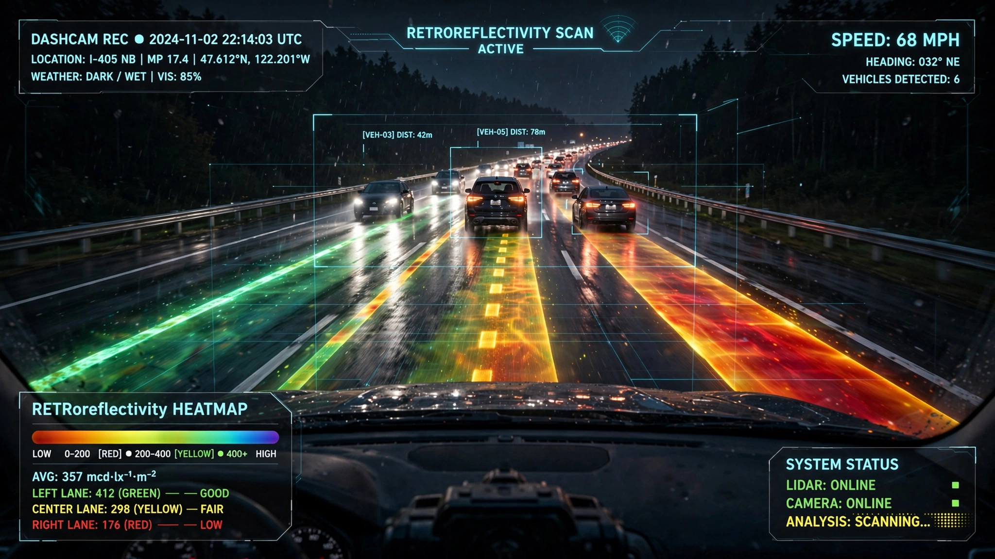
Disclosed is a system and method for continuous, network-wide assessment of pavement marking retroreflectivity using consumer dashcams and fleet vehicle forward-facing cameras as distributed photometric sensors. Each participating vehicle's headlight-camera system is computationally modeled as an uncalibrated retroreflectometer: the known luminous intensity distribution of the vehicle's headlamps (retrieved from a vehicle-specific headlight database indexed by make, model, year, and headlamp configuration) serves as the illumination source, while the dashcam's CMOS sensor (characterized by a one-time radiometric self-calibration using the road surface as a Lambertian reference) serves as the photometric detector. For each video frame captured during nighttime driving, the system segments pavement markings from surrounding asphalt using a lightweight semantic segmentation model, estimates the measurement geometry (observation angle, entrance angle, measurement distance) from the camera's known mounting position and road geometry derived from vanishing point analysis, and computes the coefficient of retroreflected luminance (RL) in mcd·m−2·lux−1 by solving the photometric equation relating observed pixel brightness to retroreflectivity given the estimated illuminance at the marking surface. Fleet-scale aggregation across thousands of vehicles produces a continuously updated RL map of every marked road segment, with temporal degradation curves fitted per segment using Bayesian regression. A maintenance prioritization engine combines RL estimates with traffic volume data, crash history, weather exposure, and road classification to generate ranked restriping work orders, replacing the current paradigm of annual surveys with dedicated $40,000+ mobile retroreflectometers.
Field of the Invention
This invention relates to transportation infrastructure monitoring, specifically to methods for repurposing consumer and fleet vehicle camera systems as distributed pavement marking retroreflectometers through computational photometric calibration of the headlight-marking-camera optical chain, with fleet-scale data aggregation and degradation-aware maintenance scheduling.
Background
Pavement markings are the primary visual guidance system for 230 million licensed drivers in the United States. At night, when approximately 50% of fatal crashes occur despite only 25% of vehicle miles traveled (NHTSA, 2023), drivers depend almost entirely on the retroreflective properties of lane markings to maintain lane position. Retroreflectivity describes a material's ability to redirect incident light back toward its source. Pavement markings achieve this through glass beads embedded in paint or thermoplastic that act as retroreflectors when illuminated by vehicle headlights.
The coefficient of retroreflected luminance (RL) is the standard metric, measured in millicandelas per square meter per lux (mcd·m−2·lux−1). Fresh white markings typically measure 300–500 mcd·m−2·lux−1, degrading with traffic wear, UV exposure, and weather. The Manual on Uniform Traffic Control Devices (MUTCD) established minimum maintained retroreflectivity standards in 2010: 100 mcd·m−2·lux−1 for white markings on roads with speed limits ≥35 mph (using 30-meter geometry), and 50 mcd·m−2·lux−1 for yellow markings. These thresholds represent the minimum visibility at which an average driver can detect markings in time to react at the posted speed.
Current retroreflectivity measurement methods are expensive and infrequent:
- Handheld retroreflectometers: Devices such as the RoadVista LaserLux G7 or Delta LTL-M measure RL at a single point per placement. Cost: $15,000–$25,000 per unit. A trained operator can measure approximately 50–100 points per day, meaning a statewide survey of 200,000 lane-miles requires thousands of person-days.
- Mobile retroreflectometers (MRUs): Vehicle-mounted systems such as the Delta LTL-M MRU or RoadVista G7 Mobile measure continuously at highway speeds. Cost: $40,000–$100,000 per unit plus a dedicated survey vehicle. FHWA-HRT-09-006 documented MRU measurement at the ASTM E1710 standard 30-meter geometry (1.05° observation angle, 88.76° entrance angle). Most state DOTs survey their networks at most once per year; many survey only a statistical sample.
- Visual nighttime inspections: MUTCD Section 3A.03 permits "calibrated visual assessment" as an alternative to instrumental measurement. Trained inspectors drive at night and rate marking visibility on a qualitative scale. Subjective, non-repeatable, and provides no quantitative RL values.
The result is a critical safety infrastructure monitored by annual snapshots at best. Between surveys, markings degrade unpredictably based on traffic volume, pavement type, marking material, climate, and snowplow operations. A marking that measured 150 mcd·m−2·lux−1 in October may drop below 50 mcd·m−2·lux−1 by February in northern states, creating invisible lane markings precisely when wet/snowy conditions make them most critical.
Meanwhile, the ADAS (Advanced Driver Assistance Systems) and autonomous vehicle industries have created a massive installed base of calibrated forward-facing cameras. As of 2025, approximately 75 million vehicles on US roads have forward-facing cameras, including dashcams, ADAS cameras (lane departure warning, lane keeping assist), and fleet telematics cameras. These cameras observe pavement markings billions of times per night, but discard the photometric information after lane detection. No existing system treats this fleet as a distributed retroreflectivity sensing network.
Prior work in camera-based retroreflectivity estimation has focused on dedicated survey vehicles. WO2014096398A1 (LKAB Wassara) describes a vehicle-mounted camera system for multiline retroreflection measurement using calibrated illumination and a pixel intensity mapping function. US6674878B2 (Swarco) describes automated retroreflectivity determination of road signs and markings using dedicated high-output light sources and calibrated sensors. Both require purpose-built hardware on dedicated survey vehicles, not crowdsourced consumer cameras.
The gap in the art is a system that: (a) uses unmodified consumer dashcams and fleet cameras as retroreflectometers through computational photometric calibration, (b) aggregates measurements from a vehicle fleet for continuous network-wide coverage, (c) models temporal degradation to predict when markings will fall below MUTCD thresholds, and (d) generates prioritized maintenance schedules that account for safety risk, not just RL values.
Detailed Description
1. Headlight-Camera Photometric Model
The fundamental measurement principle exploits the physics of retroreflection. When a vehicle's headlights illuminate a pavement marking, the glass beads embedded in the marking retroreflect light back toward the vehicle. A forward-facing dashcam, positioned near the headlights on the same vehicle, captures a portion of this retroreflected light. The pixel brightness of the marking in the dashcam image is proportional to the marking's retroreflectivity (RL), the headlight illuminance at the marking surface, and the camera's radiometric response.
The photometric equation relating these quantities is:
RL = Lmeasured / Emarking
where Lmeasured is the luminance of the marking as observed by the camera (cd/m²), and Emarking is the illuminance at the marking surface from the headlights (lux). To compute RL from a dashcam image, the system must estimate both quantities.
Headlight illuminance estimation: Each vehicle model has a characteristic headlight luminous intensity distribution (LID) defined by the headlamp assembly's optics, bulb type (halogen, HID, LED), and beam pattern (low beam vs. high beam). The system maintains a Vehicle Headlight Database indexed by make, model, year, and trim level, containing the LID as a function of horizontal and vertical angle (typically from photogoniometric data published in IES LM-79 test reports, NHTSA headlamp compliance test data, or reverse-engineered from manufacturer specifications). Given the vehicle's identity (provided during user onboarding or detected from OBD-II VIN), the system looks up the LID and computes the illuminance at any point on the road surface as:
E(x,y) = I(θh, θv) · cos(α) / d²
where I(θh, θv) is the luminous intensity at horizontal angle θh and vertical angle θv from the headlight axis, d is the distance from headlight to marking, and α is the angle of incidence on the road surface. The headlight height, lateral separation, and aim angle are vehicle-specific parameters stored in the database.
Camera radiometric calibration: Converting pixel brightness to luminance requires characterizing the camera's radiometric response function (the mapping from scene luminance to pixel value, including lens transmission, sensor quantum efficiency, Bayer filter response, ISP gamma curve, and auto-exposure settings). The system performs a one-time self-calibration by imaging a section of dry asphalt (a near-Lambertian diffuse reflector with known typical albedo 0.05–0.12 for dark asphalt) under the vehicle's own headlights. The asphalt luminance is computed from the headlight illuminance model, and the camera's response function is fitted as a monotonic spline mapping pixel value to luminance. Auto-exposure metadata (ISO, shutter speed, gain) from the dashcam's EXIF data or video metadata stream corrects for frame-to-frame exposure variations.
2. Measurement Geometry Estimation
RL is geometry-dependent: the ASTM E1710 standard specifies measurement at 30-meter distance with 1.05° observation angle and 88.76° entrance angle. A dashcam mounted on a windshield at height hcam ≈ 1.2 m observes markings at varying distances from directly ahead to the vanishing point. The system computes the observation angle (angle between the illumination direction and the observation direction) and entrance angle (angle between the illumination direction and the marking surface normal) for each marking pixel using:
- Camera intrinsics: Focal length, principal point, and lens distortion coefficients, obtained from a one-time calibration or estimated from the dashcam model's known specifications.
- Camera extrinsics: Height, pitch, and yaw of the camera relative to the road surface, estimated dynamically from vanishing point detection. The lane markings' convergence point in the image directly encodes the camera's pitch and yaw. Lee et al. (2012, IEEE T-ITS) demonstrated sub-degree pitch estimation from lane vanishing points.
- Distance estimation: For each marking pixel, the distance from the camera (and from the headlights, given their known offset) is computed via the inverse perspective mapping (IPM) using the estimated camera height and pitch. At typical dashcam mounting positions, markings at 20–50 meters ahead provide observation and entrance angles within ±15° of the ASTM E1710 standard geometry.
For measurements taken at non-standard geometry, a geometry correction function maps the observed RL to the equivalent RL at standard 30-meter geometry. This function is empirically derived from fleet measurements of the same marking segment by vehicles with different camera mounting positions and heights (sedans vs. SUVs vs. trucks), which inherently observe the marking at different geometries. The cross-vehicle consistency constraint enables the system to learn the geometry correction without dedicated calibration targets.
3. Pavement Marking Segmentation and Classification
A lightweight semantic segmentation model (architecture: MobileNetV3 backbone with a decoder head, ~2.5 million parameters, INT8 quantized to ~2.5 MB) runs on each dashcam frame to identify and classify pavement marking pixels. The model distinguishes:
- Marking types: Solid white, dashed white, solid yellow, dashed yellow, crosswalk, stop bar, turn arrow, text/symbol, edge line.
- Marking vs. non-marking: The model is trained to differentiate actual pavement markings from visually similar features (concrete joints, oil stains, tire marks, road patches, puddle reflections) that could produce false retroreflectivity measurements.
- Marking condition: Binary classification of "intact" vs. "absent/severely degraded" for segments where marking material is expected (based on road classification and historical mapping) but not detected. This captures total marking loss, not just RL degradation.
Each detected marking segment is assigned a geographic location (latitude, longitude) and a linear reference (route ID + milepost) using map-matched GPS from the dashcam or connected smartphone. Marking segments are discretized into 10-meter road intervals for consistent fleet-wide aggregation.
4. Fleet-Scale Aggregation and Temporal Degradation Modeling
Individual vehicle measurements are noisy due to headlight variability, camera exposure fluctuations, wet vs. dry conditions, and geometric approximations. The system achieves measurement-grade accuracy through fleet-scale statistical aggregation:
- Per-segment RL estimation: For each 10-meter road segment, measurements from multiple vehicles over a configurable window (default: 7 days) are aggregated using a robust estimator (trimmed mean or Huber M-estimator) that downweights outliers from wet conditions, dirty windshields, or miscalibrated vehicles. A minimum of 5 independent vehicle measurements within the window is required for a valid RL estimate.
- Vehicle calibration consistency: Vehicles that consistently produce RL estimates outside the fleet consensus for the same road segments are flagged for recalibration. This cross-validation mechanism detects headlight degradation (yellowed lenses, misaimed beams), dirty dashcam lenses, and systematic calibration errors without requiring ground-truth retroreflectometer data.
- Wet-surface rejection: Measurements taken during or immediately after precipitation are flagged and excluded from the RL aggregation. Wet detection uses: (a) wiper activation status from OBD-II or CAN bus data, (b) precipitation detected via rain-on-windshield visual classification, and (c) correlation with weather API data (OpenWeatherMap, NWS) for the segment's location and time.
Temporal degradation modeling: For each road segment, the system fits a Bayesian degradation curve to the time-series of RL estimates. The degradation model is:
RL(t) = RL,0 · exp(−λ · t) + ε(t)
where RL,0 is the initial retroreflectivity after restriping, λ is the degradation rate (day−1), and ε(t) captures measurement noise. The degradation rate λ is modeled as a function of covariates: average daily traffic (ADT), heavy vehicle percentage, pavement type (asphalt vs. concrete), marking material (paint vs. thermoplastic vs. epoxy vs. polyurea), climate zone, and cumulative snowplow passes. The Bayesian framework produces posterior predictive distributions for future RL, enabling the system to predict when each segment will fall below the MUTCD minimum threshold with calibrated uncertainty.
5. Maintenance Prioritization Engine
The system generates prioritized restriping work orders by computing a Marking Safety Risk Score (MSRS) for each road segment that integrates:
- Current RL deficit: (RL,threshold − RL,current) / RL,threshold, clamped to [0, 1]. Segments above threshold score 0.
- Time to threshold crossing: Expected number of days until RL(t) drops below the MUTCD minimum, from the Bayesian degradation model. Segments predicted to cross within 30 days receive higher priority.
- Traffic exposure: ADT × segment length, representing the number of driver-exposures to the degraded marking per day.
- Crash history: Weighted count of nighttime, run-off-road, and cross-centerline crashes within 0.1 miles over the preceding 5 years, from state crash databases linked via the MMUCC standard.
- Road classification and speed: Higher-speed roads with narrower lanes receive greater weight, as marking visibility is more critical for lane-keeping at speed.
- Curve and grade: Segments on horizontal curves or significant grades receive a multiplier reflecting the greater lane-keeping demand.
The MSRS is computed as a weighted sum: MSRS = w1·deficit + w2·urgency + w3·exposure + w4·crash + w5·speed + w6·geometry, with weights configurable by the maintaining agency. Default weights are derived from the relationship between marking retroreflectivity and crash rates established by Carlson et al. (2013, Transportation Research Record), who found a statistically significant increase in nighttime crash rates on road segments where RL fell below 100 mcd·m−2·lux−1.
Work orders are optimized for route efficiency using a traveling-salesman-variant algorithm that groups geographically proximate segments into contiguous restriping runs, minimizing mobilization costs and traffic control setup. The optimizer respects constraints: seasonal marking windows (no application below 50°F pavement temperature), traffic management requirements (no restriping during peak hours on high-ADT routes), and agency budget limits.
6. ADAS and Autonomous Vehicle Integration
The continuously updated RL map serves as a real-time input to ADAS and autonomous driving systems:
- Lane detection confidence adjustment: When the map indicates low RL on the approaching road segment, the ADAS system preemptively reduces its confidence in camera-based lane detection and increases reliance on radar, LiDAR, or HD map lane boundaries. This prevents sudden lane departure warnings or steering interventions when faded markings cause momentary lane detection loss.
- Operational design domain (ODD) assessment: Autonomous vehicles use the RL map to determine whether their camera-based lane-keeping system can operate safely on a given road segment at night. Segments with RL below a vehicle-specific threshold trigger a request for driver takeover (Level 3) or route avoidance (Level 4).
- Sensor fusion weighting: In multi-sensor autonomous driving stacks, the camera weight in the lane position estimate is dynamically adjusted based on the expected marking visibility from the RL map, preventing overreliance on visual lane detection on poorly marked roads.
7. Figures Description
- Figure 1: System architecture showing the headlight-marking-camera optical chain for a single vehicle, with the photometric equation and geometry angles labeled. Illustrates the headlight LID cone, the retroreflection from embedded glass beads, and the dashcam field of view.
- Figure 2: Fleet aggregation pipeline showing individual vehicle RL measurements (with noise) converging to a robust per-segment estimate as the number of contributing vehicles increases. Includes a plot of measurement variance vs. number of independent vehicles (expected to follow 1/√N scaling).
- Figure 3: Example RL degradation curve for a road segment showing fleet measurements (scatter), the Bayesian regression fit (mean and 95% credible interval), the MUTCD minimum threshold (dashed line), and the predicted threshold-crossing date with uncertainty.
- Figure 4: City-scale RL heatmap showing marking retroreflectivity by road segment, with color coding from green (>200 mcd·m−2·lux−1) through yellow (100–200) to red (<100), overlaid with high-MSRS priority segments highlighted.
- Figure 5: Geometry correction diagram showing how vehicles of different heights (sedan at 1.1 m, SUV at 1.4 m, truck at 2.0 m camera height) observe the same marking at different observation and entrance angles, and how the system normalizes these to the standard 30-meter geometry using the cross-vehicle consistency constraint.
Claims
- A system for continuous assessment of pavement marking retroreflectivity across a road network, comprising: a fleet of vehicles, each equipped with a forward-facing camera and headlights; a vehicle headlight database storing luminous intensity distributions indexed by vehicle make, model, year, and headlamp configuration; a photometric calibration module that models each vehicle's headlight-camera system as an uncalibrated retroreflectometer by computing headlight illuminance at the road surface from the stored luminous intensity distribution and estimating camera radiometric response from auto-exposure metadata and a road-surface reference calibration; and a retroreflectivity computation module that estimates the coefficient of retroreflected luminance (RL) for pavement markings detected in each camera frame by solving the photometric equation relating observed pixel brightness to retroreflectivity given the computed illuminance and calibrated camera response.
- The system of claim 1, wherein measurement geometry (observation angle, entrance angle, measurement distance) for each marking pixel is estimated dynamically from vanishing point detection in the camera image and the camera's known mounting position relative to the vehicle's headlights, and a geometry correction function normalizes measured RL values to the standard ASTM E1710 30-meter geometry.
- The system of claim 2, wherein the geometry correction function is learned empirically from fleet measurements of the same road segments by vehicles with different camera mounting heights and positions, using the cross-vehicle consistency constraint that the same marking segment should yield the same geometry-corrected RL regardless of the observing vehicle.
- The system of claim 1, further comprising a fleet aggregation module that combines RL measurements from multiple vehicles for each road segment using a robust statistical estimator, with wet-surface rejection based on wiper activation status, visual rain detection, or weather API correlation, and cross-vehicle calibration consistency monitoring that flags vehicles producing systematically biased measurements.
- The system of claim 1, further comprising a temporal degradation model that fits a Bayesian regression to the time-series of aggregated RL estimates for each road segment, with degradation rate modeled as a function of traffic volume, heavy vehicle percentage, marking material, pavement type, climate zone, and cumulative snowplow passes, producing posterior predictive distributions for future RL values and predicted dates of threshold crossing.
- A method for prioritizing pavement marking maintenance, comprising: collecting retroreflectivity measurements from a fleet of vehicles using the system of claim 1; computing a Marking Safety Risk Score for each road segment by combining: the current RL deficit relative to a regulatory threshold, the predicted time to threshold crossing from a temporal degradation model, traffic volume exposure, nighttime crash history, road speed classification, and horizontal curve or grade factors; ranking road segments by the computed risk score; and generating optimized restriping work orders that group geographically proximate high-priority segments into contiguous runs subject to seasonal, traffic management, and budget constraints.
- The system of claim 1, further comprising an ADAS integration module that transmits the continuously updated RL map to vehicle lane-keeping and lane departure warning systems, which adjust camera-based lane detection confidence and sensor fusion weights based on the expected marking visibility for the approaching road segment.
- The system of claim 1, wherein camera radiometric self-calibration is performed by imaging a section of dry asphalt road surface under the vehicle's own headlights, treating the asphalt as an approximate Lambertian reflector with known typical albedo, and fitting the camera's response function as a monotonic spline mapping pixel values to luminance.
- The system of claim 1, wherein a semantic segmentation model running on the dashcam or a connected edge processor classifies each marking pixel by marking type (solid white, dashed white, solid yellow, dashed yellow, crosswalk, stop bar, turn arrow, edge line) and marking condition (intact vs. absent/severely degraded), and wherein detection of absent markings on road segments where markings are expected from historical mapping triggers a marking-missing alert independent of RL measurement.
- The system of claim 1, wherein the vehicle headlight database is bootstrapped from publicly available photogoniometric test data, NHTSA headlamp compliance records, and IES LM-79 test reports, and is continuously refined using fleet self-calibration data from known-RL reference segments where ground-truth retroreflectometer measurements have been performed.
- The method of claim 6, wherein the maintenance prioritization engine incorporates the cost-effectiveness of different marking materials (paint, thermoplastic, epoxy, polyurea, tape) by predicting the expected service life and degradation trajectory of each material on each road segment based on its specific traffic, climate, and pavement conditions, enabling the system to recommend the most cost-effective marking material for each restriping job.
Implementation Notes
The on-device processing pipeline is designed for existing dashcam hardware. The semantic segmentation model (MobileNetV3 backbone, ~2.5 MB INT8) runs at 10 fps on Qualcomm QCS6490 or comparable dashcam SoCs, consuming <100 mW incremental power. Only compressed measurement packets are transmitted (road segment ID, RL estimate, measurement geometry, confidence score, timestamp, GPS coordinates): approximately 200 bytes per segment per frame, or ~2 KB/km of nighttime driving. For a vehicle driving 30 km at night, total data transmission is ~60 KB per trip.
Privacy: the system transmits only aggregated photometric measurements per road segment. No raw video, no images of other vehicles or pedestrians, and no detailed trip traces are collected. The measurement packet contains only the road segment identifier (a public infrastructure entity, not a user-identifying datum), the RL estimate, and a timestamp.
Validation pathway: agencies can deploy ground-truth retroreflectometer measurements on a sample of road segments and compare against fleet-estimated RL values. Preliminary analysis of the photometric calibration chain suggests achievable accuracy of ±30 mcd·m−2·lux−1 per individual vehicle measurement, improving to ±10 mcd·m−2·lux−1 with 10+ vehicle aggregation, sufficient for MUTCD compliance assessment where the critical threshold is 100 mcd·m−2·lux−1.
Prior Art References
- NHTSA Traffic Safety Facts — Nighttime crash fatality statistics
- Manual on Uniform Traffic Control Devices (MUTCD) — Federal pavement marking retroreflectivity standards
- MUTCD Section 3A.03 — Maintained minimum retroreflectivity levels for pavement markings
- FHWA-HRT-09-006 — Field evaluation of mobile retroreflectometers for pavement markings
- Carlson et al. (2013, Transportation Research Record) — Relationship between pavement marking retroreflectivity and nighttime crash rates
- Lee et al. (2012, IEEE T-ITS) — Vanishing point detection for camera pitch estimation
- WO2014096398A1 — Vehicle-mounted system for multiline retroreflection measurement (dedicated survey vehicle)
- US6674878B2 — Automated retroreflectivity determination of road signs using dedicated hardware
- ASTM E1710-18 — Standard test method for measurement of retroreflective pavement marking materials with CEN-prescribed geometry
- IES LM-79 — Approved method for electrical and photometric measurements of solid-state lighting products
- MMUCC — Model minimum uniform crash criteria for linking crash databases
- RoadVista LaserLux G7 — Handheld retroreflectometer product specifications