System and Method for Diagnosing Evaporative Cooler Failure Modes Using Psychrometric Effectiveness, Sump Conductivity, and Motor-Current Fusion
A swamp cooler fails in nine ways that all feel the same: the house stays hot, the air at the register feels warm, and the unit on the roof sounds like it is running. Five channels, read per run and across the season, would name the part that failed.
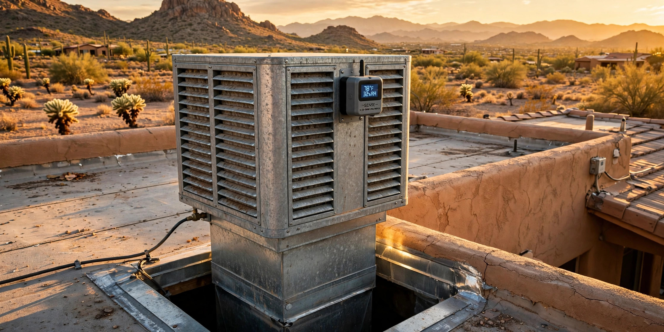
A swamp cooler can run all afternoon, sound fine, and cool nothing. The pump is dead, the pads are dry, or the belt is slipping, and the house stays hot either way. This disclosure would give the cooler a voice. November is the month to check it, while the cooler is drained and the pads are in your hands.
Just want the 30-minute checks? Skip to What a Homeowner Can Do Now. The nine causes, and how to tell them apart without sensors, are in the table in How It Fails.
Share: X · Facebook · WhatsApp · SMS · Copy link
Abstract
A proposed system would diagnose why a residential direct evaporative cooler stopped cooling, instead of merely reporting that the house is hot. Five sensing channels would be fused per run and across the season: psychrometric effectiveness from outdoor dry-bulb, wet-bulb, and supply-air temperatures; sump level and makeup flow; sump conductivity; pump current; and blower current with delivered airflow. An edge diagnostic would match the pattern across those channels against the signature of each of nine failure modes, report a named cause with the repair it requires, and track a cooling effectiveness index, measured effectiveness divided by the baseline for the installed pads, so a slow decline is visible before the house stops cooling.
Field of the Invention
This invention relates to residential evaporative cooling, specifically to a diagnostic combination for direct evaporative coolers that distinguishes the nine failure modes in Table 1 for roof-mounted and window-mounted residential units with recirculating water and belt-driven or direct-drive blowers.
Background
How Evaporative Cooling Works
A direct evaporative cooler, called a swamp cooler across the dry West, cools air by pulling it through a water-saturated pad and discharging it into the space. Water evaporating from the pad absorbs the heat of vaporization, roughly 8,700 Btu per gallon evaporated, about 1,040 Btu per pound of water, by Mississippi State Extension's count, so the airstream loses sensible heat and gains moisture. A small submersible pump recirculates water from a sump, or pan, to the top of the pad, and a blower moves 2,000 to 20,000 cubic feet per minute depending on unit size. Residential units run 3 to 8 gallons of water per hour at full operation. Electricity use lands 70 to 80 percent below comparable vapor-compression cooling, because the only loads are a fan and a small pump. That efficiency is why the machines survive: they cool a house in Phoenix for the price of running a fan.
Two thermometers define the limits of evaporative cooling. A dry-bulb thermometer measures ordinary air temperature. A wet-bulb thermometer wraps its bulb in a wet wick and reads the lowest temperature evaporation can reach. The gap between the two, called the wet-bulb depression, is the theoretical ceiling for a perfect cooler. Saturation effectiveness compares what a cooler actually delivers to what the depression allows:
ε = (Tdb − Tsupply) ÷ (Tdb − Twb)
A system operating at 80 percent saturation effectiveness delivers a temperature drop equal to 80 percent of the depression. In Phoenix on a July afternoon, dry-bulb readings near 108 degrees F with wet-bulb readings near 72 degrees F create a depression of roughly 36 degrees, so an effective direct cooler can supply air near 79 degrees F. Direct systems commonly reach 70 to 90 percent effectiveness; indirect and two-stage systems push higher because they cool air without adding as much humidity to the space. Evaporative cooling performs best where the outdoor wet-bulb temperature stays below roughly 65 to 70 degrees F during the cooling season, the design rule the U.S. Department of Energy Building America guide states.
Effectiveness depends on the pad. Pad media comes in three common forms: aspen fiber, which is cheap and short-lived; cellulose, which holds its shape and lasts several seasons; and rigid synthetic media used in industrial units. The ranges below come from manufacturer data and the ASHRAE Handbook treatment of direct evaporative equipment, as compiled by an independent cooler diagnostic site. They are ranges rather than constants, because effectiveness varies with pad material, thickness, face velocity, and condition:
| Pad type and condition | Saturation effectiveness | Notes |
|---|---|---|
| Rigid media, 8 to 12 in, well maintained | 0.85 to 0.90 | Best a direct cooler can do |
| Rigid media at 4 in, or fresh aspen fully wetted | 0.70 to 0.80 | Typical new residential unit |
| Aspen pads mid-season or partially scaled | 0.55 to 0.70 | Normal seasonal decay |
| Pads partially wetted, dry streaks | 0.40 to 0.65 | Water delivery failure, not pad age |
| Pads dry, pump dead | Near 0 | Fan only, no evaporation |
The table shows why a single effectiveness reading cannot name a cause. A reading of 0.60 could mean aspen pads halfway through a hard-water season, or rigid pads starved of water by clogged distribution tubes. The two have different repairs, and the reading alone cannot tell them apart. That ambiguity is the problem this disclosure addresses.
Two more properties of the physics matter for diagnosis. First, the sump water temperature nearly equals the wet-bulb temperature of the outside air, because the recirculating water sits in equilibrium with the air passing over it. A quick check for pad performance in the older literature is to measure the sump water temperature and apply it in place of the wet-bulb temperature in the effectiveness formula. Second, wet-bulb temperature must be computed from dry-bulb temperature, relative humidity, and local barometric pressure using the ASHRAE psychrometric relations, not from a sea-level closed-form approximation. The popular Stull approximation is a regression fit made at sea level; at 5,000 feet it returns a wet bulb about 2 degrees F too high for typical desert conditions. A wet bulb that is too high shrinks the denominator of the effectiveness formula, so computed effectiveness is inflated by roughly 7 percent: a cooler truly at 0.85 reads 0.91. The error makes a failing cooler look healthy, not a healthy one look deficient. Albuquerque sits near 5,300 feet. Santa Fe near 7,000. A diagnostic that used Stull would pass failing coolers across the high desert.
The Water Side: Evaporation, Bleed-Off, and Scale
Evaporation leaves the minerals behind. Pure water leaves as vapor, and the calcium and other dissolved solids stay in the sump and on the pads. A University of Arizona Cooperative Extension study that monitored coolers at 46 Phoenix homes averaged 7.6 gallons per operating hour, a weighted average across the homes, about half the homes having bleed-off: 4.4 gallons without bleed-off and 10.4 gallons with it, and coolers with bleed-off used about 8,650 gallons across a cooling season. Those two figures are measured averages across different homes, not a before-and-after on one unit, which is why they sit far apart from the bulletin's own guidance that adding bleed-off to one unit raises water use by an estimated 10 to 50 percent. The bleed-off homes may have been larger units or run longer hours. A Lawrence Berkeley National Laboratory review found about 400 liters, roughly 106 gallons, per household per day, which reconciles with the UA average at about 14 hours of operation a day, a plausible day of cooling.
The Department of Energy Building America guide, citing a 2007 Southwest efficiency study, estimates yearly use for a 1,500 square foot home without bleed-off at 2,980 gallons in Santa Fe, 7,261 in Albuquerque, and 12,457 in Las Cruces, and says to add 50 percent with a bleed-off valve. Note the inversion: the DOE Las Cruces figure without bleed-off exceeds the UA Phoenix with-bleed figure of 8,650 gallons, though Phoenix is hotter. The two studies used different homes, methods, and years, and the inversion is a warning against comparing figures across studies.
A bleed-off line is a small tap on the recirculating line that sends part of the pump's water to a drain, so fresh makeup water dilutes the minerals left in the sump. The University of Arizona cites a water systems manager suggesting a bleed-off rate of about one-third of makeup water, which is three cycles of concentration, lowered if no scale shows on the pads. The more efficient alternative is a dump pump, also called a purge pump, that empties the cooler pan and brings in clean water at regular intervals, such as every 8 to 12 hours of operation. The governing relation is cycles of concentration, the ratio of dissolved solids in the sump to dissolved solids in the makeup water, equal to evaporation plus bleed-off divided by bleed-off. At two cycles, half the makeup water leaves as bleed-off; at four cycles, a quarter of it does, a third of the evaporated water. Without any bleed-off or purge, the cycles climb without bound and the sump becomes increasingly aggressive scale-forming water.
Scale is the slow failure. The University of Arizona explains that scale on pads spreads water unevenly, causing hot spots and less cooling, and that the rust and corrosion from hard water may shorten a cooler's life by 50 percent. Repair guides put the performance cost at 30 percent or more: mineral deposits and biological growth restrict airflow and reduce cooling efficiency, and when air cannot pass cleanly through the wet medium, it bypasses the cooling process. Aspen pads also compress and slump under their own wet weight, closing the passages further. The failure is gradual, which is why it is missed: performance that was fine in May is disappointing by August, and the household blames the weather.
Water distribution is the most important way of prolonging pad life, according to the Munters engineering bulletin on scale and dirt control. Most distribution systems consist of a perforated plastic pipe with holes directed at a splash plate. If the pressure is low, the water will not break up at the splash plate, and streaking and dry areas will occur. Required flow is about 0.50 gallons per minute per linear foot of pad for 4-inch corrugated pads and 0.75 for 6-inch pads. For a 3-foot pad wall that is 1.5 gallons per minute, about 90 gallons per hour of recirculation, most of which returns to the sump; it is not consumption. When the pads operate properly they are thoroughly wetted with a visible flow of water trickling down the flutes. If there is little water running out the bottom of the pad, the dirt and minerals are not being flushed. The distributor pipe must be level, and where more than one pad wall is fed by the same pump they must be balanced with valves.
How It Fails: Why Nine Failures Feel Like One
The repair guides give the same order to check, and the same symptom hides the cause. A cooler that is not blowing cold air is frustrating, especially in a heat wave, but the cause is usually one of a handful of fixable problems: no power, dry or clogged pads, a pump or float issue, a worn belt, closed windows, or humid weather. The symptom table below is condensed from three independent repair guides and a diagnostic site that ranks nine causes by how often each one turns out to be the answer. The first two account for most complaints without a technician being involved.
| What you notice | Most likely cause | First thing to check |
|---|---|---|
| Nothing runs | Tripped breaker, switch setting, motor or wiring fault | Breaker and switch position |
| Fan runs, air is warm | Dry pads, dead pump, low water, high humidity | Whether the pads are evenly wet |
| Air is cool, then turns warm | Float or water supply problem, pump running dry | Water level in the sump |
| Weak airflow | Clogged pads, loose belt, no exhaust path | Belt tension and open windows |
| Musty smell | Stagnant water, algae, scale | Sump and pad condition |
| Dripping or overflow | Misadjusted or stuck float | Float arm and supply valve |
The nine failure modes this disclosure distinguishes, in the order the diagnostic site ranks them by frequency, are:
- insufficient relief air;
- pads not fully wetted, from clogged distribution tubes;
- scaled, compressed, or spent pads;
- no bleed-off or purge;
- a slipping or glazed blower belt;
- a failed or clogged recirculation pump;
- a stuck-closed float valve;
- a stuck-open float valve; and
- a blower motor bearing or capacitor failure.
Humid weather is the tenth outcome and is not a failure: when the wet-bulb depression falls below about 5 Kelvin, roughly 9 degrees F, a direct cooler gives little useful cooling and mainly humidifies, and no repair will change that.
What makes these failures hard to tell apart is that they share a symptom and share a superficial sign. The symptom is a hot house, and the sign is a cooler that appears to be running: the blower turns, the pump hums, and nothing alarms. The diagnostic site states the confusion plainly for the most common cause:
A loose or glazed belt lets the blower turn slower than rated, so delivered CFM falls well below spec while effectiveness is unaffected. The air leaving the unit is properly cold. There is simply not enough of it.
The standard advice is a manual procedure that takes about thirty minutes and a look inside the unit: check that the pads are uniformly dark and damp top to bottom, confirm the float keeps the sump at the right level, clear the distribution tubes, check that the pump moves water, check belt tension, and open a window for relief air. That procedure works, and it is the procedure this disclosure automates. The failure it addresses is not that the procedure is unknown. It is that nobody opens a roof-mounted unit until the house has been hot for weeks, because nothing in the house reports the failure, and the water a stuck float wastes in the meantime, or the pump that burns itself out running dry, accrues silently. A vacation home or a rental has nobody to run the procedure at all.
What Exists Already
Existing art covers the pieces but not the diagnosis. Level sensing for evaporative coolers is patented art: US 9,970,807 B2, granted May 15, 2018 to Essick Air Products, discloses a climate control device with an ultrasonic emitter and receiver that measures the liquid level in the receptacle and provides a liquid level indication. Its sibling, US 10,533,759 B2, granted January 14, 2020 to the same assignee, discloses a climate control device with a liquid level sensor and a controller configured to determine a change in the level of liquid, calculate an efficiency of the evaporative medium based on the change in level, and provide an efficiency indication when the efficiency falls below a predetermined value, and to operate the pump at varying liquid flow rates dependent on the evaporation rate of the medium. Both are conceded. The Essick patents disclose room-scale evaporative cooler and humidifier units, not whole-house roof-mounted coolers, and their efficiency indication is inferred from the liquid level falling, not measured from the air. A level that falls slowly could mean the pads are evaporating well or the pump is dead and the water is leaving through a leak, and the Essick controller cannot tell those apart, because it reads one channel.
Conductivity-based bleed control is established art in commercial cooling, and some residential cooler controllers meter the bleed based on conductivity. The Department of Energy guide notes automatic controllers that meter bleed-off based on conductivity, and Australian residential units from Breezair, Coolair, and Braemar dump the sump automatically when water quality declines. This disclosure concedes that a conductivity reading can trigger a purge. What none of those controllers does is use the conductivity trend as one channel in a named-cause diagnostic: a purge controller that dumps the sump treats the symptom, mineral concentration, and says nothing about whether the pads are scaled, the belt is slipping, or the float is stuck.
A manual diagnostic guide exists on the web. The site ismycoolerworking.com computes saturation effectiveness from readings the homeowner enters, ranks nine causes by frequency, and gives a confirm-it check and a fix for each, including the effectiveness bands this disclosure uses. It is conceded as a guide. It is a web calculator, not an installed system: it reads numbers a person typed in after climbing onto the roof, it has no sensor, no current measurement, no conductivity trend, and no memory of last week. A homeowner who never opens the unit never runs it.
The genuine gap is narrower than "no diagnosis exists": it is the fusion of psychrometric effectiveness measured from the air, sump conductivity, sump level and makeup, pump current, and blower current with airflow, into a named cause with a repair, for a whole-house direct evaporative cooler. A thermostat knows the indoor temperature trajectory and a circuit-level energy monitor knows the current draw, but neither knows the supply-air temperature, the sump level, or the sump conductivity, and neither names a cooler failure. No patent, product, or publication found in the search described below does that fusion.
The Search
The search behind the novelty statement covered US patent publications through November 2026, queried through Google Patents with terms combining evaporative cooler with liquid level sensor, efficiency indication, pump control, and diagnostics, and covered the European publication server for the same terms. It also covered manufacturer documentation for residential coolers, the Department of Energy Building America evaporative cooling guide, University of Arizona Cooperative Extension bulletin AZ9145, the Lawrence Berkeley National Laboratory water-use review, the ASHRAE Handbook psychrometrics chapter, the Munters engineering bulletin on scale and dirt control, the EnergyPlus engineering reference for evaporative coolers, and independent repair guides and the cooler diagnostic site cited above. It did not cover the heating, ventilation, and air-conditioning fault-detection-and-diagnostics literature, where multi-sensor signature tables are standard practice, nor commercial and industrial evaporative diagnostics, so the novelty statement covers only the residential direct evaporative cooler combination as searched. The combination it found nothing for has six elements:
- psychrometric effectiveness measured directly from outdoor dry-bulb temperature, outdoor wet-bulb temperature computed from relative humidity and barometric pressure by the ASHRAE relations, and supply-air temperature, with sump water temperature as a cross-check on the wet-bulb reading;
- sump water level and makeup flow tracked across runs, so a falling sump, a dry-running pump, and a continuously overflowing float are known from the water balance rather than from a single level reading;
- sump water conductivity tracked across the season, so cycles of concentration are known and a missing bleed-off or purge is detected from the trend rather than from a single reading;
- recirculation pump current measured against a learned baseline, so a dead, seized, clogged, or dry-running pump is distinguished by its current signature;
- blower motor current measured with delivered airflow, so a slipping belt is distinguished from a bearing or capacitor failure and from insufficient relief air by the current and airflow together; and
- an edge diagnostic that matches the pattern across those channels to a named failure cause, with a confidence and the repair that cause requires, and that reports humid weather as a no-fault outcome when the wet-bulb depression is too small for any cooler to cool.
One concession is needed on scope. Liquid level sensing, level-inferred efficiency indication, variable pump flow by evaporation rate, conductivity-metered bleed-off, automatic sump dumping, and the manual diagnostic procedure are all known, and this disclosure does not claim them. The distinction rests on the narrower combination: the five channels fused across runs and across the season, with the signatures that separate causes which present the same symptom and the same superficial signs. A level sensor alone cannot tell a dead pump from a clogged distributor, because both leave the pads dry, and a conductivity reading alone cannot tell scaled pads from a missing bleed-off, because both raise the mineral load. Only the pattern across the channels separates them, and no existing system reads that pattern.
Detailed Description
This section describes a proposed system. No prototype exists. Every threshold, rate, and cost figure in it is a design target, not a measured result. Conditional language is used deliberately throughout.
1. System Overview
Five parts would make up the system. A sensing unit mounted on the cooler would carry the outdoor temperature and humidity sensor, the supply-air temperature sensor, the sump water temperature sensor, the sump level sensor, the sump conductivity probe, the pump current sensor, the blower current sensor, and the airflow sensor. An edge diagnostic unit in the sensing unit would read those channels through each run and across the season, compare the pattern against the failure-mode signatures in section 7, and output a named cause with a confidence. A display would show the cooler state, the cooling effectiveness index, and the repair for the diagnosed cause.
A run interface would read the cooler control state, which speed the blower is set to and whether the pump is commanded on, either from the cooler controller directly or inferred from the current channels, with the inference validated as section 6 describes. A household gateway, optional, would carry the diagnosis to the homeowner by message and keep the run history. No water would be added or removed by the system, no ductwork would change, and no cloud connection would be needed for the diagnosis itself: the edge unit would name the cause in the moment, on the device, and the gateway would add only the history and the remote message. A configuration input would receive the pad type and thickness, the rated airflow, the cooler size, the makeup water hardness where known, and a pad-replacement event.
2. Psychrometric Effectiveness: The Outcome Channel
Measure effectiveness from the air, not from the water. Three temperature readings would define it: outdoor dry-bulb temperature from a sensor in the shade at the cooler intake, outdoor wet-bulb temperature computed from outdoor dry-bulb temperature, relative humidity, and local barometric pressure using the ASHRAE humidity-ratio relations solved iteratively, and supply-air dry-bulb temperature from a sensor in the discharge duct or at a supply register. Effectiveness would be computed as the outdoor dry-bulb minus the supply-air temperature, divided by the outdoor dry-bulb minus the wet-bulb temperature. The computation would run only after the pads have been pre-wetted, because a short blast of warm air at startup is normal when the pads have dried out overnight, and the standard practice is to run only the pump for a few minutes so the pads are fully saturated before the fan starts. The diagnostic would therefore wait 10 minutes after pump start before scoring effectiveness, a design-target delay, and would discard the startup transient.
The wet-bulb computation would use barometric pressure, not a sea-level assumption. At 5,000 feet the Stull closed-form approximation returns a wet bulb about 2 degrees F too high for typical desert conditions, and that error inflates computed effectiveness, as the Background section shows. The system would solve the ASHRAE relations iteratively to a tolerance far below the accuracy of any thermometer it uses, and would take barometric pressure from a local pressure sensor or from the nearest weather station, corrected for elevation. A 2-degree wet-bulb error is the difference between a failing cooler and one that passes, and the diagnostic must not pass failing coolers across the high desert.
Sump water temperature would cross-check the wet-bulb reading. The sump water nearly equals the wet-bulb temperature of the outside air, so a computed wet bulb that disagrees with the measured sump water temperature by more than 3 degrees F, a design-target tolerance, would flag a sensor fault and suspend effectiveness scoring under the rejection rules in section 11, rather than letting a bad humidity sensor condemn the pads.
Effectiveness would be scored only when the wet-bulb depression is large enough for the measurement to mean anything. When the depression falls below about 9 degrees F, roughly 5 Kelvin, a direct cooler gives little useful cooling and mainly humidifies, and the diagnostic would report the no-fault weather outcome in section 7 rather than scoring the pads. A cooler cannot be blamed for humid air. The depression floor is a rejection rule, not a failure mode.
A worked example, with illustrative numbers: a 2,000 cubic feet per minute unit, a common size for a 1,000 square foot home at the sizing rule of about 2 cubic feet per minute per square foot, on a Phoenix afternoon at 100 degrees F dry bulb and 68 degrees F wet bulb, a 32-degree depression. Rigid media at 0.85 effectiveness would supply air at 100 minus 0.85 times 32, which is 72.8 degrees F. Sensible cooling delivered would be 1.08 times 2,000 times 27.2, about 58,800 Btu per hour, roughly 4.9 tons. Evaporation at that design hour would be 1.2 times 2,000 times 27.2 divided by 10,000, about 6.5 gallons per hour by the Munters relation, inside the 3-to-8-gallon residential range. That figure is a peak design-hour rate, not an average: the University of Arizona measured 4.4 gallons per hour averaged across all operating hours, because most hours are milder than the design hour. The Munters relation implies about 9,000 Btu per gallon, 3 percent above the Mississippi State figure of 8,700; the difference is rounding in the two rules.
3. Sump Level and Makeup: The Water-Balance Channel
The sump needs a level measurement, because one level reading cannot separate the failures. An ultrasonic sensor mounted above the sump, the sensing approach US 9,970,807 B2 discloses for a receptacle, would measure the water level without contact, with a float switch as an alternative embodiment. The edge unit would record the level at four points in every run: at pump start, after 10 minutes of pre-wetting, at steady state mid-run, and at shutdown. The four-point trajectory would be the measurement, not any single reading: a sump that falls steadily across a run is a different fact from a sump read once, and a sump that never falls while the cooler runs is a different fact from a sump read at rest.
Makeup flow would be inferred from the level trajectory, not measured with a dedicated flow meter. When the pump runs and the cooler evaporates, the sump level falls and the float valve admits makeup water; the net fall over a run, plus the known evaporation from the effectiveness channel, gives the makeup rate. A sump that holds level while the cooler evaporates 4 gallons per hour is being refilled, and a sump that falls while the float valve should be admitting makeup water is not. The level sensor would report the sump level in centimeters with a resolution target of 5 millimeters, about 3/16 inch, and the diagnostic would flag a stuck-closed float when the sump level falls by more than 5 centimeters, about 2 inches, across a run while makeup should be flowing, a design-target rule chosen so a single missed reading cannot declare a float failure.
The water balance would carry the stuck-float distinction, not a second pump signal: in a stuck-closed float the sump level would fall until the pump intake sucks air, the pump current would fall to its dry-run value, and the pads would dry; in a stuck-open float the sump level would sit at the overflow standpipe, makeup flow would run continuously even with the pump off, and the conductivity would fall as fresh water dilutes the sump. A stuck-open float wastes water at a rate the homeowner never sees, because the overflow goes to a roof drain. A float valve passing 0.5 gallons per minute, a substantial leak, wastes 720 gallons per day, or 21,600 gallons in a month. The Department of Energy guide puts a whole season of cooling for a 1,500 square foot home in Las Cruces at 12,457 gallons. One stuck float wastes more water in 18 days than a season of cooling. That arithmetic is the reason the float finding matters: the leak is silent, continuous, and larger than the cooler's entire legitimate use.
An overflow switch at the standpipe would report whether the sump is at overflow, so the rejection rule in section 11 can be enforced and the stuck-open finding can be confirmed by two sensors rather than one. The float valve level would normally sit about 1 inch, 2.5 centimeters, below the pan top edge or the overflow standpipe, the setting the repair guides state.
4. Sump Conductivity: The Mineral Channel
Measure sump water conductivity continuously during operation with a probe in the sump, reported as total dissolved solids in parts per million. Conductivity is the mineral channel: evaporation leaves dissolved solids behind, so conductivity rises as water evaporates and falls when fresh makeup water dilutes the sump. The edge unit would record three values per run: conductivity at pump start, conductivity at steady state, and conductivity at shutdown. The trend across runs would be the measurement, not any single reading: a conductivity that climbs week over week is a different fact from a conductivity read once on a hot afternoon.
Cycles of concentration would be computed from the conductivity trend. Cycles equal sump conductivity divided by makeup water conductivity, where the makeup conductivity is measured once at installation or entered from a water test. At two cycles, half the makeup water leaves as bleed-off; at four cycles, a quarter of it does, a third of the evaporated water. The diagnostic would track cycles across the season against a design-target ceiling of 4 cycles, chosen because above that level the sump water is concentrated enough to scale pads rapidly in hard-water areas. A unit with no bleed-off and no purge would show cycles climbing without bound across the season, and the diagnostic would name the missing bleed-off or purge before the pads scale, not after. The edge unit would log each bleed-off and purge event with its duration, so the no-bleed finding rests on a logged absence, not a single reading.
Scaled pads and a missing bleed-off both raise the mineral load, but they differ in the conductivity trend. A cooler whose pads are spent from age or compression would show effectiveness declining while conductivity stays within its band, because the pads are failing for a mechanical reason, not a chemical one. A cooler whose bleed-off is absent would show conductivity climbing week over week while the pads are still young, because the water is concentrating faster than the pads can tolerate. The table in section 7 states that distinction as a cell: the scaled-pad row requires conductivity within band, and the no-bleed row requires conductivity above band with no bleed events logged.
The probe would sit in the sump where the water circulates, not in a dead corner, and would be cleaned on the pad-replacement schedule, because a fouled probe reads low, which is the same signature as fresh water, so the sensor could report the condition it is meant to detect. The conductivity reading would be temperature-compensated to 25 degrees C, 77 degrees F, the standard reference, using the sump water temperature sensor from section 2, because conductivity rises with temperature and an uncompensated reading would climb on hot afternoons for a reason that has nothing to do with minerals.
5. Pump Current: The Water-Delivery Channel
Measure pump current with a current-transformer clamp on the pump supply, sampled through each run. The pump is a small submersible unit, and its current signature carries four states. An electrically dead pump draws zero current while commanded on. A seized pump draws a locked-rotor spike, several times its running current, then falls to zero when its thermal cutout trips. A clogged pump, its intake screened with sediment or its impeller scaled, draws below its learned baseline while moving little water, because a centrifugal pump unloads as flow falls. A dry-running pump, its intake sucking air because the sump fell below it, draws below baseline and runs hot, and the repair guides warn that a pump run dry will burn itself out. The current sensor would report the pump state as one of those four, not as a raw ampere reading, and the edge unit would compare each run against the baseline learned in the first two weeks, as section 9 describes.
The distribution check would not use pump current. A clogged distribution tube does not change the pump current much, because the pump still moves water against the same head, and the water simply returns to the sump through the path of least resistance while one pad wall stays dry. The diagnostic would use the effectiveness channel instead: a partially wetted pad reads 0.40 to 0.65 effectiveness while the pump current reads normal, and that combination, low effectiveness with normal pump current and normal sump level, is the distribution signature. A dead pump reads low effectiveness with zero pump current, and the two differ in exactly one cell.
6. Blower Current and Airflow: The Air-Delivery Channel
Blower motor current would be measured by a current-transformer clamp on the blower supply, sampled through each run and in particular during startup. The blower is the air-delivery channel, and its current signature carries three states. A slipping or glazed belt unloads the motor: the blower turns slower than rated, delivered airflow falls, and motor current falls below its learned baseline, because a belt-driven blower with a slipping belt presents less load to the motor. That current fall holds for a permanent-split-capacitor motor; for a constant-airflow ECM motor the controller may speed up to compensate, so current is controller-dependent and static pressure carries the discrimination, as the next paragraph describes. A bearing failure loads the motor: current rises above baseline, and the startup transient stretches, because drag fights the start. A failing capacitor shows as a slow start or a failure to start, with current high and airflow zero until the motor either catches or trips. The current sensor would report the startup transient duration and the steady-state current, and the edge unit would compare both against the baseline.
Delivered airflow would be measured independently of current, because current alone cannot separate a slipping belt from a sealed house. A duct static pressure sensor, or a register air velocity sensor where the duct is inaccessible, would report delivered airflow as a fraction of the rated airflow for the blower speed setting. A slipping belt and insufficient relief air both reduce delivered airflow, but they differ in the current channel for one motor type and in the static pressure channel for the other. With a constant-airflow ECM blower, the sealed house loads the motor against high static pressure and current rises, while the belt slip unloads the motor and current is controller-dependent, so static pressure, not current, carries the discrimination for ECM motors. With the common permanent-split-capacitor motor, the current distinction fails: a centrifugal blower with a PSC motor draws less power as static pressure rises, because airflow falls faster than pressure rises, so current falls in both cases.
For PSC motors the diagnostic would separate them by duct static pressure, which the static-pressure sensor already measures: a sealed house raises static pressure above baseline while airflow falls, and a slipping belt lets static pressure fall with airflow. Relief air needs about 2 square feet of open relief per 1,000 CFM, the PNNL rule citing PG&E, so a 2,000 CFM unit needs about 4 square feet of open window or door. That distinction is why the two channels are fused. The diagnostic site puts the belt case this way: effectiveness can measure perfectly while the house stays hot, because the air leaving the unit is properly cold and there is simply not enough of it.
The run interface would record which blower speed is commanded and whether the pump is commanded on, read from the cooler controller where the controller exposes it, or inferred from the current channels where it does not. The inference would be checked against the commanded state the homeowner sets on the wall switch: a blower drawing current while the switch is off is a wiring fault, not a belt failure, and the diagnostic would report it as such. Where speed is inferred from current rather than read from the controller, the inference would be circular if left unchecked: the same channel the diagnostic scores would also define the speed. The disclosure would break that circle by validating the inferred speed against the airflow channel: a blower at high speed must deliver high airflow, and a current reading that claims high speed while airflow reads low is a belt finding, not a speed reading.
7. Edge Diagnostic: The Signature Table
Why nine failures feel like one, in a table.
Match the pattern across the five channels against the signature of each failure mode, and output the best-matching cause or causes with a confidence and the repair each cause requires. The signatures are the claimed combination, and they are stated as a table so the discrimination is inspectable rather than a black box. A pattern matches a signature when every value stated in that signature's row holds: no single channel names a cause, and a cause would be reported only when its full signature matches. A conditional cell is read against its stated condition. The dependent claims recite the discriminating subset of each signature, the cells that separate that cause from its nearest neighbor; the table states the full signature, and the edge diagnostic would apply the full signature. The rows are ordered by how often each cause turns out to be the answer, the ranking from the diagnostic site in the Background section.
Confidence would be computed only over the threshold-type cells of the matched signature: a threshold-type cell is a cell stating a numeric one-sided limit, below or above a stated value. For each such cell, the margin would be the measured value's distance past its threshold divided by the threshold, capped at 100 percent, the distance measured as the threshold minus the measured value for a below-type threshold and as the measured value minus the threshold for an above-type threshold, and the reported confidence would be the smallest such margin. Cells that state "Normal," equality, a band, zero current, or no change would contribute only a pass or a fail, not a margin. Confidence here is a margin, not a probability: it states how far each measured value sits past its threshold, not the likelihood the diagnosis is right. The display would show the margin as a band, narrow below 25, moderate from 25 to 75, wide above 75, on the capped 0-to-100 margin scale, with the percentage kept only in the raw run readings for inspection. When a matched signature has no threshold-type cell, the diagnostic would report the confidence band as moderate, with the reason stated: the signature matched on equality and band cells only, and no margin could be computed.
A worked confidence calculation, with illustrative numbers: a belt signature with delivered airflow at 55 percent of rated against a 70 percent threshold gives a margin of 15 divided by 70, about 21 percent, and blower current 30 percent below baseline against a 15 percent threshold gives a margin of 15 divided by 15, 100 percent capped. The smallest margin is 21 percent, so the display would show a narrow band.
Table 1: Failure-mode signatures. Each row is one cause; each column is one channel. A cause is reported only when every cell in its row holds. The discriminating cell in each row is shown in bold. ε = saturation effectiveness. CFM = delivered airflow as a fraction of rated airflow at the commanded speed.
| Failure mode | Effectiveness ε | Supply-air temp | Sump level | Makeup flow | Sump conductivity | Pump current | Blower current | Delivered airflow | Indoor temp trajectory |
|---|---|---|---|---|---|---|---|---|---|
| Insufficient relief air | Normal | Normal, cold at register | Normal | Below baseline | Within band | Normal | Below baseline for PSC motors; normal to high for ECM motors | Below 70% of rated, static pressure above baseline | Flat despite cold supply air |
| Clogged distribution tubes | 0.40 to 0.65 | Above the pad-type baseline | Normal | More than 25% below the learned baseline | Within band | Normal | Normal | Normal | Rising |
| Scaled, compressed, or spent pads | Declining across season, 0.55 to 0.70 for mid-season aspen | Above the pad-type baseline | Normal | Below baseline as evaporation falls | Within band | Normal | Normal | Declining as passages close | Rising |
| No bleed-off or purge | Declining across season | Above the pad-type baseline | Normal | Evaporation only, no bleed component | Above band, cycles climbing past 4 | Below baseline as scale clogs the pump | Normal | Normal | Rising |
| Slipping or glazed belt | Normal | Normal, cold at register | Normal | Below baseline, less air means less evaporation | Within band | Normal | Below baseline for PSC motors; controller-dependent for ECM motors | Below 70% of rated, static pressure below baseline | Flat despite cold supply air |
| Failed or clogged pump | Below 0.20 if dead; 0.20 to 0.40 if clogged | Near outdoor dry bulb | Normal | Near zero | Within band | Zero if dead; locked-rotor spike then zero if seized; below baseline if clogged | Normal | Normal | Rising |
| Stuck-closed float valve | Collapses once pads dry | Rises to outdoor dry bulb | Falling more than 5 cm across a run | Zero while the float valve should be admitting makeup water | Spiking as water evaporates with no makeup | Dry-run low, then zero on thermal cutout | Normal | Normal | Rising |
| Stuck-open float valve | Normal | Normal | At overflow standpipe | Continuous, far above evaporation plus bleed | Falling, diluted by fresh water | Normal | Normal | Normal | Normal |
| Blower motor bearing or capacitor | Normal while the motor runs; not scored if the motor will not start | Normal while the motor runs; not scored if the motor will not start | Normal | Normal | Within band | Normal | Above baseline if bearing drag; slow start or no start if capacitor | Declining, or zero if motor will not start | Rising |
| Humid weather, no fault | Not scored, depression below 9°F | Above comfort but consistent with ε and the depression | Normal | Low, little evaporation in humid air | Within band | Normal | Normal | Normal | Warm, depression below 9°F |
The qualitative terms in the table have quantitative definitions. "Normal" means within the baseline ratios learned in section 9: effectiveness within 0.05 absolute of the learned baseline, delivered airflow at or above 70 percent of rated, pump and blower current within 15 percent of baseline, and sump conductivity within the band learned after a fresh fill, the band being within 20 percent of the post-fill baseline. Makeup flow is normal within 25 percent of the learned baseline, and "Below baseline" for makeup means more than 25 percent below the learned baseline, in every row, and for pump and blower current means more than 15 percent below the learned baseline. "Above the pad-type baseline" for supply-air temperature means above the temperature corresponding to the learned baseline effectiveness by more than the 3-degree-F sensor tolerance. "Declining across season" means the cooling effectiveness index falls by more than 0.05, in absolute index points, per week across four weeks, scored in the onset window, the first weeks after the failure begins. "Declining" for delivered airflow means falling by more than 10 percent across four weeks. "Near zero" for effectiveness means below 0.20, the cooler delivering essentially no evaporative cooling. A reading of exactly 0.40 is assigned to the pump row, not the partially-wetted band.
"Rising" for indoor temperature means the indoor sensor reads a rise of more than 1 degree F over the first hour of a run. "Flat" means the indoor temperature changes by no more than 1 degree F in either direction over the first hour of a run. "Warm" means the indoor temperature reads above 80 degrees F with the wet-bulb depression below 9 degrees F. "Spiking" for conductivity means rising more than 25 percent above the upper edge of the learned band within a single run. "Far above" for makeup means more than twice evaporation plus bleed. "Low" for makeup means more than 25 percent below the learned baseline. "Continuous" for makeup means flowing while the pump is off. "Above band" means above the upper edge of the learned band.
The table also states what the diagnostic would not do. Each pair of confusable causes differs in exactly one cell: pump current for a dead pump versus a clogged distributor, conductivity for scaled pads versus a missing bleed-off, blower current for ECM motors or duct static pressure for PSC motors for a slipping belt versus a sealed house, and sump level for a stuck-closed float versus a dead pump.
When two signatures hold at once, the diagnostic would report both causes in order of confidence and would say the pattern is ambiguous rather than picking one: a cooler with scaled pads and a missing bleed-off is a real possibility, and the bleed-off is often the reason the pads scaled. When no signature holds, the diagnostic would report unknown cause with the raw run readings, rather than guessing.
A confident wrong answer is worse than an honest pair.
The season tells the same story in numbers: a cooler whose rigid-media pads read 0.87 effectiveness in May and 0.58 four weeks later, while sump conductivity triples across the same weeks, from 1.5 to 4.5 cycles of concentration, and no bleed-off events are logged. The effectiveness decline is 0.29 across four weeks, and the index falls from 1.00 to 0.67, 0.083 per week, past the 0.05-per-week decline rule, which is stated in index points. The conductivity trend puts cycles past 4. The diagnostic would name the missing bleed-off as the primary cause. Scaled pads would be named as the damaged component in the repair order, not as a second matched signature, because the scaled-pads row requires conductivity within band and the conductivity here is above band. The repair order follows the same logic: restore the bleed-off first, then replace the pads, because new pads in the same concentrated water would scale again by September.
8. Cooling Effectiveness Index
Track a cooling effectiveness index, defined as measured saturation effectiveness divided by the reference baseline effectiveness for the installed pad type, thickness, and condition, the reference baseline being the midpoint of the band in the Background table: 0.87 for 8-to-12-inch rigid media, 0.75 for 4-inch rigid media or fresh aspen, 0.62 for aspen mid-season. A new cooler should read near 1.0. In plain terms, an index of 1.0 means the cooler delivers its rated effectiveness; 0.8 means one-fifth of the pad's cooling is gone; 0.7 means nearly a third is gone. An index that falls to 0.7 would mean the supply air runs about 8 degrees F warmer than rated on a 32-degree-depression afternoon, because a 0.3 index shortfall against a 0.87 baseline is 0.26 effectiveness points, and 0.26 times 32 is about 8. An index that falls by more than 0.05, in absolute index points, per week across four weeks would count as a steady decline, meaning the pads are losing wetted surface, whatever the supply-air reading on any single afternoon says.
The baseline is the condition the pads are in, not the condition they were in: a mid-season aspen cooler at 0.62 reads an index of 1.0, because normal seasonal decay is not a failure. A slow fall from 0.75 to 0.62 across a season is normal aging, not a failure; the decline rule fires only on a fall faster than 0.05 index points per week. The index would be reported after every run, with its four-week trend, so a slow decline would be visible before the house stops cooling. The index would be suspended, not reported, while any rejection rule in section 11 holds, because an index computed from a run that never pre-wetted the pads measures the startup transient, not the pads.
9. Baseline Learning: The First Two Weeks
Learn the baselines from the first two weeks of operation after installation or after a pad replacement, because fixed thresholds cannot hold across cooler sizes, pad types, duct lengths, and water hardness. During that window the homeowner would confirm the cooler is healthy, pads uniformly wet, sump at the right level, belt tensioned, by answering one prompt on the display. The baselines learned would be: effectiveness per wet-bulb depression band, pump current at steady state, blower current at each speed with its startup transient duration, delivered airflow at each speed, duct static pressure at each speed, sump conductivity after a fresh fill, and makeup flow per run at the local climate. A baseline would be set only from runs that deliver cold supply air, effectiveness inside the band for fresh pads of the installed type, with the sump at the right level and no overflow. The diagnostic would refuse to set a baseline from a failing cooler, and would keep prompting until two healthy weeks are recorded. The learned baseline must itself sit inside the Background band for the installed pad type and condition, else the baseline is rejected: a partially wetted aspen cooler reading 0.60 sits inside the mid-season band but outside the fresh-aspen band, and it must not set a degraded baseline.
Baselines would be re-learned after a pad or belt replacement, and the diagnostic would suspend pad-wear findings for 14 days after a pad replacement, so new pads are not condemned for the break-in readings of their first runs.
10. Display, Gateway, and Fleet Learning
Show one state per cooler on the display: healthy with the cooling effectiveness index and the wet-bulb depression, or a named failure cause with a confidence shown as a margin band, narrow below 25, moderate from 25 to 75, wide above 75, on the capped 0-to-100 margin scale, rather than a percentage or a probability, a repair, and the run readings behind it, the repair following a manufacturer procedure for that cause. The display would show a date of a last pad inspection, prompt the homeowner to inspect the pads monthly, show a calibration-due state when the conductivity probe is past a cleaning interval of 6 months, and show the cooler state as unverified, not healthy, while the probe is past that interval or no pad inspection has been recorded in 90 days, and while the baseline is still learning. A green healthy state could give false confidence, because the household that trusts the display stops opening the unit, and the display is the thing that can be wrong. The last-inspection date and the monthly prompt are the mitigations, and they answer the objection only if the homeowner acts on them.
The gateway would carry the named failure cause to the homeowner by message, store the run history locally, comprising effectiveness per run, the cooling effectiveness index trend, sump conductivity trend, and every diagnosed cause with its date, and minimize the payload on-device before upload, stripping timestamps and per-run volumes.
A fleet service would receive, only with explicit opt-in on a screen naming the fleet operator and the data sent, a failure mode, a cooler model, a pad type, a makeup water hardness value, and run readings from a plurality of households. Household identity would be replaced with a rotating pseudonym that rotates monthly, derived on-device from a household secret the gateway never transmits, with no server-side household-to-pseudonym table. Records would be stored encrypted at rest and in transit and retained no longer than 24 months.
On withdrawal, the gateway would present a deletion token, from which the fleet service derives the household's past rotating pseudonyms and deletes the matching records, including backups and processors within 30 days, and issues a deletion receipt. The deletion token would be single-use, transmitted only over the encrypted channel, and never logged. The deletion covers the household's records and future aggregates, but not aggregates already published before withdrawal, and the household is told this at opt-in. Opt-in would require notice to all occupants, by a posted notice in the home and a contact address at which a tenant may object, and a tenant's objection would withdraw the household; an objection or withdrawal would block re-enrollment until a fresh opt-in by the homeowner after 90 days. The fleet service would report only aggregate failure likelihoods per cooler model and per water chemistry, each aggregate built from no fewer than ten households in the same model-by-chemistry slice. The fleet learning could answer the question no single household can answer, which cooler models scale fastest on which water, and which pad types hold effectiveness longest, where a slice reaches ten households. Some of the protections in this section are promises about how a future operator would behave, not properties of the system: on-device pseudonym derivation, local storage, and on-device minimization are properties of the system, while no-sale, deletion, and the 10-household floor remain operator promises.
11. Scoring Rejection Rules
Suspend scoring, not report a cause, while any of these rules holds: while the pads have not yet pre-wetted, the first 10 minutes after pump start; while the wet-bulb depression is below 9 degrees F, the no-fault weather outcome applying instead; while a cooler access panel is open; while the conductivity probe reports a calibration fault or has been dry; for 14 days after a pad-replacement event recorded through the configuration input; for 48 hours after a fresh sump fill, while the conductivity baseline re-settles; while the blower is off or the cooler is in fan-only mode with the pump commanded off; while no water use occurs, the cooler idle; while an inferred blower speed fails validation against the airflow channel; and while the sump water temperature disagrees with the computed wet-bulb temperature by more than 3 degrees F, the sensor disagreement rule in section 2. Each suspension would be logged with its reason and the diagnosis reported as paused.
Claims
In patent language, that system is claimed as follows. The dependent claims below recite the discriminating subset of each signature in Table 1, the cells that separate that cause from its nearest neighbor; the table states the full signature.
- A system for diagnosing failure modes of a direct evaporative cooler, comprising: an outdoor temperature and humidity sensor configured to measure outdoor dry-bulb temperature and outdoor relative humidity at a cooler intake; a barometric pressure input configured to receive local barometric pressure from a pressure sensor or from a weather station corrected for elevation; a supply-air temperature sensor configured to measure supply-air dry-bulb temperature in a discharge duct or at a supply register of the cooler; a sump water temperature sensor configured to measure sump water temperature in a sump of the cooler; a sump level sensor configured to measure a sump water level in the sump, the measurements being recorded at a pump start, after 10 minutes of pre-wetting, at steady state mid-run, and at shutdown of a run; an overflow switch configured to detect whether the sump water level is at an overflow standpipe; a sump conductivity probe configured to measure sump water conductivity as total dissolved solids in parts per million, temperature-compensated to 25 degrees C using the sump water temperature; a makeup conductivity input configured to receive a makeup water conductivity value measured once at installation or entered from a water test; a pump current sensor configured to measure recirculation pump current through each run; a blower current sensor configured to measure blower motor current through each run including a startup transient duration; an airflow sensor configured to measure delivered airflow as a fraction of a rated airflow at a commanded blower speed; an indoor temperature input configured to receive an indoor temperature trajectory over a first hour of a run from a temperature sensor or a thermostat; a run interface configured to read a cooler control state recording which blower speed is commanded and whether a recirculation pump is commanded on, the cooler control state being read from a cooler controller where the cooler exposes it or inferred from the pump current and blower current, and to compare the inferred blower speed against the delivered airflow; an input configured to receive a pad type and thickness, a rated airflow, a cooler size in cubic feet per minute, a makeup water hardness value, and a pad-replacement event for the cooler; and an edge diagnostic unit; wherein the edge diagnostic unit computes a wet-bulb temperature from the outdoor dry-bulb temperature, the outdoor relative humidity, and the local barometric pressure using ASHRAE humidity-ratio relations solved iteratively, and computes a saturation effectiveness as the outdoor dry-bulb temperature minus the supply-air dry-bulb temperature, divided by the outdoor dry-bulb temperature minus the wet-bulb temperature, after 10 minutes of pre-wetting; computes a cooling effectiveness index as the saturation effectiveness divided by a reference baseline effectiveness for the pad type, thickness, and condition, the reference baseline being the midpoint of the band for the pad type, thickness, and condition, 0.87 for 8-to-12-inch rigid media, 0.75 for 4-inch rigid media or fresh aspen, 0.62 for aspen mid-season; computes cycles of concentration as the sump water conductivity divided by the makeup water conductivity.
- The system of claim 1, wherein the edge diagnostic unit compares a pattern of the saturation effectiveness, the supply-air dry-bulb temperature, the sump water level, a makeup flow inferred from the sump water level trajectory, the sump water conductivity, the recirculation pump current, the blower motor current, the delivered airflow, and the indoor temperature trajectory against a signature table stating, for each measured value, a value or a threshold, wherein a pattern matches a signature when every value stated in that signature's row holds, a conditional cell being read against its stated condition, and wherein 'normal' for a measured value means saturation effectiveness within 0.05 absolute of a learned baseline effectiveness, learned from two weeks of operation after installation or after a pad-replacement event, the two weeks containing only runs that deliver supply-air temperature consistent with the reference baseline effectiveness for fresh pads of the pad type, with the sump water level at the float-valve set level and no overflow, delivered airflow at or above 70 percent of the rated airflow, pump current and blower current within 15 percent of a learned current baseline, and sump water conductivity within a band learned after a fresh fill; and outputs at least one named failure cause with a confidence value, the confidence value being the smallest margin across the threshold-type cells of the signature, a threshold-type cell being a cell stating a numeric one-sided limit, below or above a stated value, each margin being the measured value's distance past its threshold divided by the threshold, capped at 100 percent, the distance measured as the threshold minus the measured value for a below-type threshold and as the measured value minus the threshold for an above-type threshold, cells stating 'Normal,' equality, a band, zero current, or no change contributing only a pass or a fail, and the confidence value being reported as a moderate band with the reason stated when a matched signature has no threshold-type cell, the named failure cause being selected from a failed or clogged recirculation pump, clogged distribution tubes, scaled or spent pads, absent bleed-off or purge, a slipping blower belt, a stuck-closed float valve, a stuck-open float valve, a blower motor bearing or capacitor failure, and insufficient relief air, only when the pattern matches the signature of that cause in the signature table, and outputs a no-fault weather outcome, rather than a named failure cause, when the wet-bulb depression, the outdoor dry-bulb temperature minus the wet-bulb temperature, is below 9 degrees F.
- The system of claim 2, wherein the edge diagnostic unit compares the saturation effectiveness against the reference baseline effectiveness for the pad type and thickness, and the signature table distinguishes the clogged distribution tubes from the failed or clogged recirculation pump by the recirculation pump current, the clogged distribution tubes holding the saturation effectiveness in a 0.40 to 0.65 band while the recirculation pump current reads normal, and the failed or clogged recirculation pump holding the saturation effectiveness below 0.20 if dead or 0.20 to 0.40 if clogged while the recirculation pump current reads zero if dead, a locked-rotor spike then zero if seized, or below baseline if clogged.
- The system of claim 2, wherein the signature table distinguishes the scaled or spent pads from the absent bleed-off or purge by the sump water conductivity, the scaled or spent pads showing the saturation effectiveness declining across a season while the sump water conductivity stays within the band learned after a fresh fill, and the absent bleed-off or purge showing the saturation effectiveness declining across the season while the sump water conductivity rises above the band with the cycles of concentration climbing past 4 and no bleed-off or purge event logged by the edge diagnostic unit.
- The system of claim 2, wherein the signature table distinguishes the slipping blower belt from the insufficient relief air by the blower motor current and the duct static pressure, the slipping blower belt holding the saturation effectiveness normal with cold supply air while the delivered airflow reads below 70 percent of the rated airflow, the blower motor current reading below baseline for a permanent-split-capacitor motor and controller-dependent for a constant-airflow motor, and the duct static pressure reading below baseline, and the insufficient relief air holding the saturation effectiveness normal with cold supply air while the delivered airflow reads below 70 percent of the rated airflow, the blower motor current reading below baseline for a permanent-split-capacitor motor and normal to high for a constant-airflow motor, and the duct static pressure reading above baseline.
- The system of claim 2, wherein the edge diagnostic unit reports the stuck-closed float valve only when the sump water level falls by more than 5 centimeters across a run while the float valve should be admitting makeup water, the recirculation pump current reads dry-run low and then zero on thermal cutout, and the saturation effectiveness collapses once the pads dry, and reports the stuck-open float valve only when the sump water level sits at the overflow standpipe, the makeup flow runs continuously while the recirculation pump is commanded off, and the sump water conductivity falls as fresh water dilutes the sump.
- The system of claim 2, wherein the edge diagnostic unit reports the blower motor bearing or capacitor failure only when the delivered airflow reads declining or zero, and the blower motor current reads above baseline with a startup transient duration more than twice the learned baseline if a bearing has failed, or a slow start or no start with current high and airflow zero if a capacitor has failed, and the saturation effectiveness is not scored where the motor will not start.
- The system of claim 2, wherein the edge diagnostic unit reports the scaled or spent pads only when the saturation effectiveness declines across the season, the sump water level reads normal, the recirculation pump current reads normal, the blower motor current reads normal, the delivered airflow reads declining as passages close, and the cooling effectiveness index falls by more than 0.05, in absolute index points, per week across four weeks.
- The system of claim 2, wherein the edge diagnostic unit learns a baseline from two weeks of operation after installation or after a pad-replacement event, the two weeks containing only runs that deliver supply-air temperature consistent with the reference baseline effectiveness for fresh pads of the pad type, compares later run readings against the baseline as ratios, and refuses to set the baseline until two healthy weeks are recorded.
- The system of claim 2, wherein the edge diagnostic unit reports two failure causes in order of confidence, and states that the pattern is ambiguous, when the signatures of two causes hold at once, and reports unknown cause with the run readings when no signature holds.
- The system of claim 2, further comprising scoring rejection rules that suspend diagnosis while the pads have not yet pre-wetted, the first 10 minutes after pump start, while the wet-bulb depression is below 9 degrees F, while a cooler access panel is open, while the sump conductivity probe reports a calibration fault or has been dry, for 14 days after a pad-replacement event recorded through the input, for 48 hours after a fresh sump fill, while the blower is off or the cooler is in fan-only mode with the recirculation pump commanded off, while no water use occurs, while an inferred blower speed fails validation against the delivered airflow, and while the sump water temperature disagrees with the computed wet-bulb temperature by more than 3 degrees F, and that log each suspension with its reason and report diagnosis as paused.
- The system of claim 2, further comprising a display that shows one state per cooler, the state being healthy with the cooling effectiveness index and the wet-bulb depression, or a named failure cause with a confidence shown as a margin band, narrow below 25, moderate from 25 to 75, wide above 75, on the capped 0-to-100 margin scale, rather than a percentage or a probability, a repair, and the run readings behind it, the repair following a manufacturer procedure for that cause, and that shows a date of a last pad inspection, prompts a user to inspect the pads monthly, shows a calibration-due state when the sump conductivity probe is past a cleaning interval of 6 months, and shows the cooler state as unverified, not healthy, while the sump conductivity probe is past that interval or no pad inspection has been recorded in 90 days, and shows the cooler state as unverified, not healthy, while the baseline is still learning, and reports no cooling effectiveness index until the baseline is set.
- The system of claim 2, further comprising a gateway that carries the named failure cause to a homeowner by message, stores the run history locally on the gateway, the run history comprising saturation effectiveness per run, the cooling effectiveness index trend, sump water conductivity trend, and every diagnosed cause with its date, and minimizes the payload on-device before upload, stripping timestamps and per-run volumes; and a fleet service that receives, only with explicit opt-in performed by the homeowner on a screen naming the fleet operator and the data sent, a failure mode, a cooler model, a pad type, a makeup water hardness value, and run readings from a plurality of households, replaces household identity with a rotating pseudonym that rotates monthly, the rotating pseudonym being derived on-device from a household secret the gateway never transmits, with no server-side household-to-pseudonym table, stores records encrypted at rest and in transit and retains them no longer than 24 months, deletes a household's records on withdrawal of opt-in, the gateway presenting a deletion token from which the fleet service derives the household's past rotating pseudonyms and deletes the matching records, deletion covering backups and processors within 30 days, and issues a deletion receipt on withdrawal stating the records deleted, reports only aggregate failure likelihoods per cooler model and per water chemistry, each aggregate being built from no fewer than ten households in the same model-by-chemistry slice, and correlates failure modes with water chemistry and cooler model.
- A method for diagnosing failure modes of a direct evaporative cooler, comprising: measuring outdoor dry-bulb temperature and outdoor relative humidity at a cooler intake and receiving local barometric pressure from a pressure sensor or from a weather station corrected for elevation; measuring supply-air dry-bulb temperature in a discharge duct or at a supply register of the cooler; measuring sump water temperature in a sump of the cooler; measuring a sump water level in the sump at a pump start, after 10 minutes of pre-wetting, at steady state mid-run, and at shutdown of a run; detecting whether the sump water level is at an overflow standpipe; measuring sump water conductivity as total dissolved solids in parts per million, temperature-compensated to 25 degrees C using the sump water temperature; receiving a makeup water conductivity value measured once at installation or entered from a water test; measuring recirculation pump current through each run; measuring blower motor current through each run including a startup transient duration; measuring delivered airflow as a fraction of a rated airflow at a commanded blower speed; receiving an indoor temperature trajectory over a first hour of a run from a temperature sensor or a thermostat; reading a cooler control state recording which blower speed is commanded and whether a recirculation pump is commanded on, the cooler control state being read from a cooler controller where the cooler exposes it or inferred from the pump current and blower current, and comparing the inferred blower speed against the delivered airflow; receiving a pad type and thickness, a rated airflow, a cooler size in cubic feet per minute, a makeup water hardness value, and a pad-replacement event for the cooler; computing, in an edge diagnostic unit, a wet-bulb temperature from the outdoor dry-bulb temperature, the outdoor relative humidity, and the local barometric pressure using ASHRAE humidity-ratio relations solved iteratively, and a saturation effectiveness as the outdoor dry-bulb temperature minus the supply-air dry-bulb temperature, divided by the outdoor dry-bulb temperature minus the wet-bulb temperature, after 10 minutes of pre-wetting; computing a cooling effectiveness index as the saturation effectiveness divided by a reference baseline effectiveness for the pad type, thickness, and condition, the reference baseline being the midpoint of the band for the pad type, thickness, and condition; computing cycles of concentration as the sump water conductivity divided by the makeup water conductivity; comparing a pattern of the saturation effectiveness, the supply-air dry-bulb temperature, the sump water level, a makeup flow inferred from the sump water level trajectory, the sump water conductivity, the recirculation pump current, the blower motor current, the delivered airflow, and the indoor temperature trajectory against a signature table stating, for each measured value, a value or a threshold, wherein a pattern matches a signature when every value stated in that signature's row holds, a conditional cell being read against its stated condition; and outputting at least one named failure cause with a confidence value, the confidence value being the smallest margin across the threshold-type cells of the signature, a threshold-type cell being a cell stating a numeric one-sided limit, below or above a stated value, each margin being the measured value's distance past its threshold divided by the threshold, capped at 100 percent, the distance measured as the threshold minus the measured value for a below-type threshold and as the measured value minus the threshold for an above-type threshold, cells stating 'Normal,' equality, a band, zero current, or no change contributing only a pass or a fail, and the confidence value being reported as a moderate band with the reason stated when a matched signature has no threshold-type cell, the named failure cause being selected from a failed or clogged recirculation pump, clogged distribution tubes, scaled or spent pads, absent bleed-off or purge, a slipping blower belt, a stuck-closed float valve, a stuck-open float valve, a blower motor bearing or capacitor failure, and insufficient relief air, only when the pattern matches the signature of that cause in the signature table, and outputting a no-fault weather outcome, rather than a named failure cause, when the wet-bulb depression, the outdoor dry-bulb temperature minus the wet-bulb temperature, is below 9 degrees F; suspending diagnosis while the pads have not yet pre-wetted, the first 10 minutes after pump start, while the wet-bulb depression is below 9 degrees F, while a cooler access panel is open, while the sump conductivity probe reports a calibration fault or has been dry, for 14 days after a pad-replacement event, for 48 hours after a fresh sump fill, while the blower is off or the cooler is in fan-only mode with the recirculation pump commanded off, while no water use occurs, while an inferred blower speed fails validation against the delivered airflow, and while the sump water temperature disagrees with the computed wet-bulb temperature by more than 3 degrees F; providing a gateway and a fleet service; replacing household identity with a rotating pseudonym that rotates monthly, deriving the rotating pseudonym on-device from a household secret never transmitted, with no server-side household-to-pseudonym table; uploading the failure mode and run readings to a fleet service, minimizing the payload on-device before upload, stripping timestamps and per-run volumes; requiring opt-in by the homeowner; suppressing aggregates built from fewer than ten households in a model-by-chemistry slice; presenting a deletion token on withdrawal, the fleet service deriving the household's past rotating pseudonyms from the deletion token and deleting the matching records, deletion covering backups and processors within 30 days; and issuing a deletion receipt on withdrawal.
Implementation Notes
The claims above describe the system; this section states how it would be built. Bill of materials for the sensing unit targets 80 to 95 dollars in volume, with the parts below as the basis for that target. The bill-of-materials figures are volume targets, not sourced costs.
| Part | Volume cost target |
|---|---|
| Outdoor temperature and humidity sensor | about 6 dollars |
| Supply-air temperature sensor | about 3 dollars |
| Sump water temperature sensor | about 3 dollars |
| Ultrasonic sump level sensor | 9 to 16 dollars |
| Sump conductivity probe | 12 to 20 dollars |
| Pump current-transformer clamp | about 4 dollars |
| Blower current-transformer clamp | about 4 dollars |
| Duct static pressure sensor | about 8 dollars |
| Indoor temperature sensor | about 3 dollars |
| Microcontroller with radio | about 10 dollars |
| Display | about 8 dollars |
| Enclosure, wiring, power | about 10 dollars |
The conductivity probe deserves a qualifier the table does not show: the 12-to-20-dollar figure is a volume target, and a probe bought singly typically costs more, while probe cleaning is maintenance the homeowner must do on a schedule, so the 80-to-95-dollar target covers the unit, not its upkeep. The edge diagnostic targets under 100 kilobytes, small enough to run on the sensing unit microcontroller, with run readings stored locally for the most recent 90 days of operation. The run interface would read the control state from the cooler controller where the controller exposes it, and would otherwise infer blower speed and pump state from the current channels, validated as section 6 describes. The display would show one state, one cause, one repair, and the cooling effectiveness index. The sensing unit would draw power from the cooler control circuit where available, and otherwise from a mains adapter, because the sump area is wet and a battery the homeowner must change would itself become a failure mode.
Calibration discipline matters more than sensor quality. The conductivity probe must be cleaned on installation and every 6 months after, a design-target interval, with an independent water test every 90 days, because a fouled probe reads low and a low reading reports concentrated water as fresh. The baseline must be learned from two healthy weeks, because fixed thresholds cannot hold across cooler sizes, pad types, duct lengths, and water hardness. The sump level sensor must be mounted so the pad spray cannot confuse it, and the supply-air temperature sensor must sit in the discharge airstream, not against the duct wall. The diagnostic unit must enforce the rejection rules in section 11, and must refuse to set a baseline from a failing cooler.
Limitations
This disclosure describes an unbuilt system. No prototype has been constructed, no accuracy figure has been measured, and every threshold in it is a proposed value. The 0.40-to-0.65 partially-wetted band, the 70 percent airflow and 15 percent current ratios, the 5-centimeter sump fall and 5-millimeter level resolution, the 4-cycle concentration ceiling, the 9-degree-F depression floor, the 10-minute pre-wet delay, the two-week baseline window, the 0.05-per-week decline rule, and the 80-to-95-dollar bill of materials are design targets, not measured results. The signature table is a hypothesis about how the failure modes separate in practice: it is built from the manufacturers' troubleshooting tables, the repair guides, and the diagnostic site's ranked causes, not from measured run data on failing coolers, and no dataset of labeled failures exists at scale to test it. Collecting one would require instrumenting coolers, waiting for them to fail in each of the nine modes, and labeling the outcomes, and a cooler takes a season or more to fail in the slow modes, so the dataset grows one failure at a time. That collection effort is the largest barrier to building this system.
Sensor error is unbudgeted. A conductivity probe would foul with scale and biofilm and read low, which is the same signature as fresh water, so the sensor could report the condition it is meant to detect. The probe would need cleaning on a schedule the homeowner must keep, and a homeowner who never opens the unit will not keep it. The outdoor humidity sensor would drift with age and dust, and a drifted humidity sensor would compute a wrong wet bulb, which would score a healthy cooler as failed or a failed cooler as healthy. The sump level measurement would read the top of a moving, splashing surface, not a flat one, and the pump return flow would ripple the reading. The airflow sensor would sit in a duct that carries dust and, in hard-water homes, mineral carryover. A fouled airflow sensor would read low, which is the same signature as a slipping belt, so the sensor could report the failure it is meant to detect. The cooling effectiveness index would depend on the pad type the homeowner programs. A homeowner who programs rigid media for aspen pads would see an index that never reaches 1.0 for a reason that has nothing to do with the pads.
The blower-speed inference in section 6 is also untested: no data shows that inferred speed would match the commanded speed closely enough to score signatures against, and a belt that slips gradually may produce a current reading the validation accepts while the airflow is wrong. The wet-bulb computation depends on a barometric pressure reading, and a pressure sensor that drifts with temperature would bias the wet bulb the same way the Stull approximation does.
Finally, the system would diagnose the cooler, not the house. It could not detect a rusted-through sump pan, a duct leak losing cold air into the attic, a cooler sized too small for the household, or a house with no relief-air path because every window is painted shut. None of those is a failure mode in the signature table. It would not test the biology of the sump water: a stagnant sump can harbor bacteria, and this system measures chemistry, not biology. This disclosure states no warranty, redress, or liability for a wrong diagnosis. The homeowner would bear the cost of a wrong repair, highest for a rental or vacation home, where a false healthy verdict leaves a hot house running for weeks. A wrong diagnosis that delays the right repair can also cause water damage: a misdiagnosed stuck float can overflow a roof-mounted cooler for a season. The homeowner checks in the final section involve roof access, live wiring, and a moving blower; the checks assume power off at the breaker before touching the unit, and a homeowner uncomfortable on a roof should hire a technician.
Strongest Case Against
The honest objection is that a look inside the unit already solves this problem in thirty minutes, and a hundred-dollar sensor suite with a fouling probe is an elaborate workaround for a check that works. The repair guides lay out the procedure in order: look at the pads, check the float, clear the tubes, check the pump, check the belt, open a window. Every cause in the signature table has a manual check that costs nothing and takes minutes, and the manual check is definitive in a way a sensor inference is not:
Pads that are uniformly dark and damp top to bottom are wet. No model required.
A sensor that names the wrong cause sends the homeowner down the wrong repair, and the most expensive wrong answer in the table is the pads, a replacement for a belt that a tension check would have fixed. No test of this system exists, so that objection stands as a reason not to build it. The argument for building it is a hypothesis: that silent failure is the real cost, because a cooler can run hot for weeks before anyone climbs onto the roof, and the pump that burns itself out running dry in those weeks does not come back when the float is fixed, and because a vacation home or a rental has nobody to run the thirty-minute procedure at all. No data in this disclosure tests that.
A second objection is the probe. The conductivity channel is the mineral channel, and it is also the least reliable channel in the system: the fouling, drift, and cleaning needs stated in Limitations apply to the very channel the no-bleed finding depends on, while the manual check the disclosure competes with, looking at the pads, needs no calibration at all. A system whose mineral channel needs regular cleaning by the same homeowner who never noticed the cooler failed is a system that will itself fail silently, and a fouled probe that reads low will report concentrated water as fresh while the pads scale. A third objection is behavioral: a green healthy state could give false confidence, as section 10 states, and the mitigations answer it only if the homeowner acts on them.
A fourth objection is that the signature table is unvalidated. Every cell in Table 1 is a prediction about how a failure would read on instruments that have never been pointed at a failing cooler in that combination. The belt row, the relief-air row, and the conductivity rows rest on reasoning from the guides, not on measured run data, and the "every cell must hold" rule cuts both ways: a real failure that presents one cell off, a belt slip on a cooler with an oversized blower, or a scaled pad on a home with soft water, would be reported as unknown cause, which is honest but not useful. Until someone instruments coolers and waits for them to fail in each of the nine modes, the table is a hypothesis with a clean shape and no evidence behind it.
A fifth objection is the fleet data. Section 10 concedes that cooler model and water hardness can identify a household to someone who knows the local water, and that run patterns can show when a home is empty. A rotating pseudonym slows that correlation without preventing it, and a small fleet makes it worse, not better. The timestamp stripping in section 10 reduces that signal without eliminating it. Some of the privacy protections in section 10 are promises about how a future operator would behave, not properties of the system: on-device pseudonym derivation, local storage, and on-device minimization are properties of the system, while no-sale, deletion, and the 10-household floor remain operator promises, and a homeowner who opts in is trusting a company not to sell the one dataset that shows when their house is vacant. That objection stands on its own even if the diagnostic works.
A sixth objection is legal, and it is the strongest one against the patent-style framing. Every element in the system is known: liquid level sensing, level-inferred efficiency indication, variable pump flow by evaporation rate, conductivity-metered bleed-off, automatic sump dumping, and the manual diagnostic procedure with its nine ranked causes. The obviousness attack under 35 U.S.C. § 103 writes itself, framed under Graham v. John Deere: the scope and content of the prior art, the differences between the art and the claims, the level of ordinary skill, and any objective indicia. A person of ordinary skill, given a known level sensor, a known conductivity probe, and a known troubleshooting table, would combine them into a diagnostic that reads the table automatically, and under KSR the combination of familiar elements yielding only their predictable results is obvious. The combination's only answer is that the discriminating power lies in the five-channel fusion itself, that no one combined these channels this way, and that the fusion separates causes the individual elements cannot, a synergistic result the elements do not predict singly. US 10,533,759 B2 infers efficiency from a falling liquid level in a room-scale unit, while the claimed system measures effectiveness from the air in a whole-house cooler and fuses it with conductivity, level trajectory, pump current, and blower current with airflow. For a defensive disclosure, that answer is enough, because publication is the point: the document exists to put the combination into the prior art whether or not it would survive examination.
A seventh objection is safety. The thirty-minute manual procedure the disclosure automates is also a procedure that puts a homeowner on a roof, at a live 120- or 240-volt circuit, beside a moving blower, with a stagnant sump that can harbor bacteria. The safety box in the final section states the precautions, but a diagnostic that tells a homeowner to open the unit is also telling them to take those risks, and the cost of a wrong diagnosis includes the cost of the check itself. That objection stands even if the diagnostic works.
A gauge that caught some failures early would beat a roof inspection nobody does, but only if the gauge works, which is unproven, and only if nobody mistakes the gauge for an inspection, which nothing in this disclosure can guarantee.
What a Homeowner Can Do Now
None of this needs to be built before it helps. Run these checks at the end of the season, while the cooler is drained and the pads are in your hands, and the findings will be fresh for May.
- Look at the pads with the cooler running: cut power to remove the panels, then restore power to observe, keeping hands clear of the blower. They should be uniformly dark and damp top to bottom. Dry patches or streaks are the diagnosis, and they mean water is not reaching part of the pad.
- Run only the pump for about 10 minutes before starting the fan, so the pads are fully saturated. A short blast of warm air at startup is normal when the pads dried out overnight.
- Check the sump water level: it should sit about 1 inch below the pan top edge, and the float valve should shut the supply off at that level. A sump that keeps falling means the float is stuck closed; a sump at the overflow with water running means it is stuck open.
- Clear the distribution tubes, with the pump switched off, if any pad wall stays dry while the pump runs: hard-water minerals scale the narrow passages, and a vinegar flush dissolves light scale.
- Check belt tension on belt-driven models: a belt that squeals on startup or lets the blower turn slowly is slipping, and the air will feel cold at the register while the house stays hot.
- Open a window or a door on the far side of the house for relief air. A sealed house pressurizes, airflow collapses, and the cooler cannot move air no matter how cold the pads are.
- Check the weather before blaming the cooler: when the wet-bulb depression is small, on a humid afternoon, no direct cooler can cool much, and the unit is not broken.
- Replace aspen pads every season and rigid media every few seasons, sooner on hard water. Pads that are crusty, white, stiff, or matted are spent, and good pads are pliable and open.
- Drain the sump and flush it at the end of the season, and scrub the pan. Stagnant water grows algae, smells musty, and scales the pump.
- Test after every repair: a fix is confirmed by cold air at the register and a house that cools down, not by the sound of the unit running.
The checks above cost nothing but half an hour and a look inside the unit. A service call that names the wrong part costs the same as one that names the right one: the national average repair bill is $198, with most jobs between $104 and $299, a pump replacement $80 to $200, and a belt $40 to $100 (Angi, 2026, 539 verified projects).
Know a renter, a landlord, or a vacation-home owner whose house stays hot all August while the cooler hums on the roof? Send them this.
Share: X · Facebook · WhatsApp · SMS · Copy link
What does not exist is a cooler that says which part failed.
Prior Art References
- US 9,970,807 B2, Climate Control Device With Improved Liquid Level Sensing (Essick Air Products, granted May 15, 2018): ultrasonic emitter and receiver measuring liquid level in a receptacle, controller providing a liquid level indication; priority January 28, 2016; expired, fee related
- US 10,533,759 B2, Climate Control Device (Essick Air Products, granted January 14, 2020): controller determining a change in liquid level, calculating an efficiency of the evaporative medium based on the change in level, providing an efficiency indication when efficiency falls below a predetermined value, and operating the pump at varying liquid flow rates dependent on the evaporation rate; priority January 28, 2016; active, expires December 11, 2037 (adjusted)
- US 2017/0219410 A1, Climate Control Device With Improved Liquid Level Sensing (Thomas, Essick Air Products, published August 3, 2017): published application of US 9,970,807 B2, ultrasonic liquid level sensing in an evaporative cooler or humidifier
- US 2020/0116368 A1, Climate Control Device (Scott Thomas, Essick Air Products, published April 16, 2020): divisional of US 15/416,336, a climate control device with a liquid level sensor and a controller calculating evaporative medium efficiency from a change in liquid level; abandoned
- U.S. Department of Energy Building America Solution Center, Evaporative Cooling Systems (PNNL resource guide, updated December 29, 2022): effectiveness equals outdoor temperature minus leaving air, divided by outdoor temperature minus wet bulb; performs best where the outdoor wet-bulb temperature stays below roughly 65 to 70 degrees F; water use for a 1,500 square foot home, 2,980 gallons a season in Santa Fe, 7,261 in Albuquerque, 12,457 in Las Cruces, 50 percent more with a bleed-off valve; dump pump empties the pan every 8 to 12 hours; about 2 square feet of open relief per 1,000 CFM
- University of Arizona Cooperative Extension AZ9145, Evaporative Coolers (1994): Phoenix coolers averaged 4.4 gallons per operating hour without bleed-off and 10.4 gallons with it across 46 homes, 7.6 gallons average; bleed-off systems used about 8,650 gallons over a cooling season; bleed-off raises water use by an estimated 10 to 50 percent; scale on pads spreads water unevenly causing hot spots and less cooling, and rust and corrosion from hard water may shorten a cooler's life by 50 percent; Lawrence Berkeley National Laboratory review finding about 400 liters, roughly 106 gallons, per household per day
- Is My Cooler Working, About and Methodology: saturation vapor pressure by the Hyland-Wexler formulation from the ASHRAE Handbook, Fundamentals; wet-bulb temperature solved iteratively by bisection against the ASHRAE humidity-ratio relation; Stull's closed-form approximation returns a wet bulb about 2 degrees F too high at 5,000 feet for typical desert conditions; effectiveness bands, 0.85 to 0.90 rigid media 8 to 12 inches, 0.70 to 0.80 rigid media at 4 inches or fresh aspen, 0.55 to 0.70 aspen mid-season
- Is My Cooler Working, Why a Swamp Cooler Stops Cooling, 9 Causes Ranked by Frequency: not enough relief air as the most common cause; pads not fully wetted, measured effectiveness in the 0.40 to 0.65 band; scaled, compressed, or spent pads, performance fine in May and disappointing by August; no bleed-off or purge; slipping or glazed blower belt, effectiveness perfect while the house stays hot
- Munters Engineering Bulletin MB-SCP-205, Controlling Scale and Dirt in Evaporative Pads: proper water distribution as the single most important way of prolonging pad life; required water flow 0.50 gallons per minute per linear foot for 4-inch corrugated pads, 0.75 for 6-inch pads; gallons per hour evaporated equals 1.2 times CFM times entering minus leaving dry bulb, divided by 10,000; cycles of concentration equals evaporation plus bleed-off, divided by bleed-off; distributor pipe must be level, pads thoroughly wetted with visible flow trickling down the flutes
- EnergyPlus 9.3.0 Engineering Reference, Evaporative Coolers: direct evaporative cooler model with rigid media pad, water recirculated from a reservoir; saturation efficiency defined as entering dry bulb minus leaving dry bulb, divided by entering dry bulb minus entering wet bulb
- ISHRAE Journal, Direct Evaporative Cooling (July to September 2007): direct evaporative cooling adiabatic efficiency of 60 to 80 percent depending on pad media and face velocity; sump water temperature nearly equals the wet-bulb temperature of outside air, used as a quick check for pad performance; aspen fiber pads 25 to 50 millimeters thick, rigid pads 100 to 300 millimeters thick, fiber pads below 1 meter per second face velocity, rigid pads up to 3 meters per second
- Evaporative Coolers for Buildings: Performance, Climate Fit, and Water Use: pad media in three forms, aspen fiber, cellulose, and rigid synthetic media; wet-bulb depression as the theoretical ceiling; direct systems 70 to 90 percent effectiveness; fan 2,000 to 20,000 cubic feet per minute; residential water use 3 to 8 gallons per hour; electricity use 70 to 80 percent below vapor-compression cooling; bleed-off metered by conductivity on automatic controllers
- Evaporative Cooling Efficiency: Formula, Examples, Limits: efficiency equals outdoor dry bulb minus supply air, divided by outdoor dry bulb minus wet bulb; direct rigid media pads about 80 to 90 percent, thin fiber pads about 60 to 80 percent, indirect about 60 to 80 percent; below about 5 Kelvin wet-bulb depression a direct cooler gives little useful cooling and mainly humidifies
- Evaporative Cooling Pad Performance Example, Perth Design Conditions: 44.5 degrees C dry bulb and 22.5 degrees C wet bulb, air velocity 2.5 meters per second, saturation efficiency 84 percent for 100 millimeter rigid media, pad air-off temperature 26.0 degrees C
- Swamp Cooler Not Blowing Cold Air? 9 Causes and Fixes: symptom-to-cause table; short blast of warm air at startup normal when pads dried out overnight, run only the pump for a few minutes first
- Why Is My Swamp Cooler Blowing Hot Air?: pump clogged with sediment or electrically failed; float stuck closed leaves the pan dry and the pump burns out, stuck open overflows continuously; distribution tubes scaled with calcium and lime; mineral deposits and biological growth reduce cooling efficiency by 30 percent or more
- How to Fix a Swamp Cooler: Common Problems and Repairs: float valve set about 1 inch below the pan top edge or the overflow standpipe; constant trickle into the pan when the pump is off indicates float failure; blower motor overheating or excessive current draw indicates worn bearings or a failing capacitor
- Swamp Cooler Repair in Fresno, CA: seven faults accounting for most service calls, pads spent or scaled as the most common by a distance, failed or clogged pump, stuck float valve, blocked distribution lines, motor bearings or belt, rusted or leaking pan, musty smell from stagnant water
- How Often Does Evaporative Cooler Dump Water: evaporative coolers typically dump water every 6 to 12 hours to prevent mineral buildup; some units use sensors to monitor water quality, triggering dumping when mineral levels rise; Breezair, Coolair, and Braemar models dump automatically on water quality or after a set period
- Evaporative Cooler vs AC: Which Works Where?: Mississippi State Extension, roughly 8,700 Btu of heat leaves with every gallon evaporated; Building America water use examples and bleed-off guidance, citing the 2007 Southwest efficiency study
- Angi, How Much Does It Cost to Repair a Swamp Cooler? (updated September 16, 2026): national average repair cost $198, typical range $104 to $299, pump repair or replacement $80 to $200, belt replacement $40 to $100, motor replacement $150 to $400, based on 539 verified projects
- 35 U.S.C. § 102(a)(1): defensive prior art under the America Invents Act, printed publications as prior art