System and Method for Localizing Air Leakage Sites in Residential HVAC Ductwork Using Acoustic Pulse Reflectometry and Machine-Learned Reflection Classification
Abstract
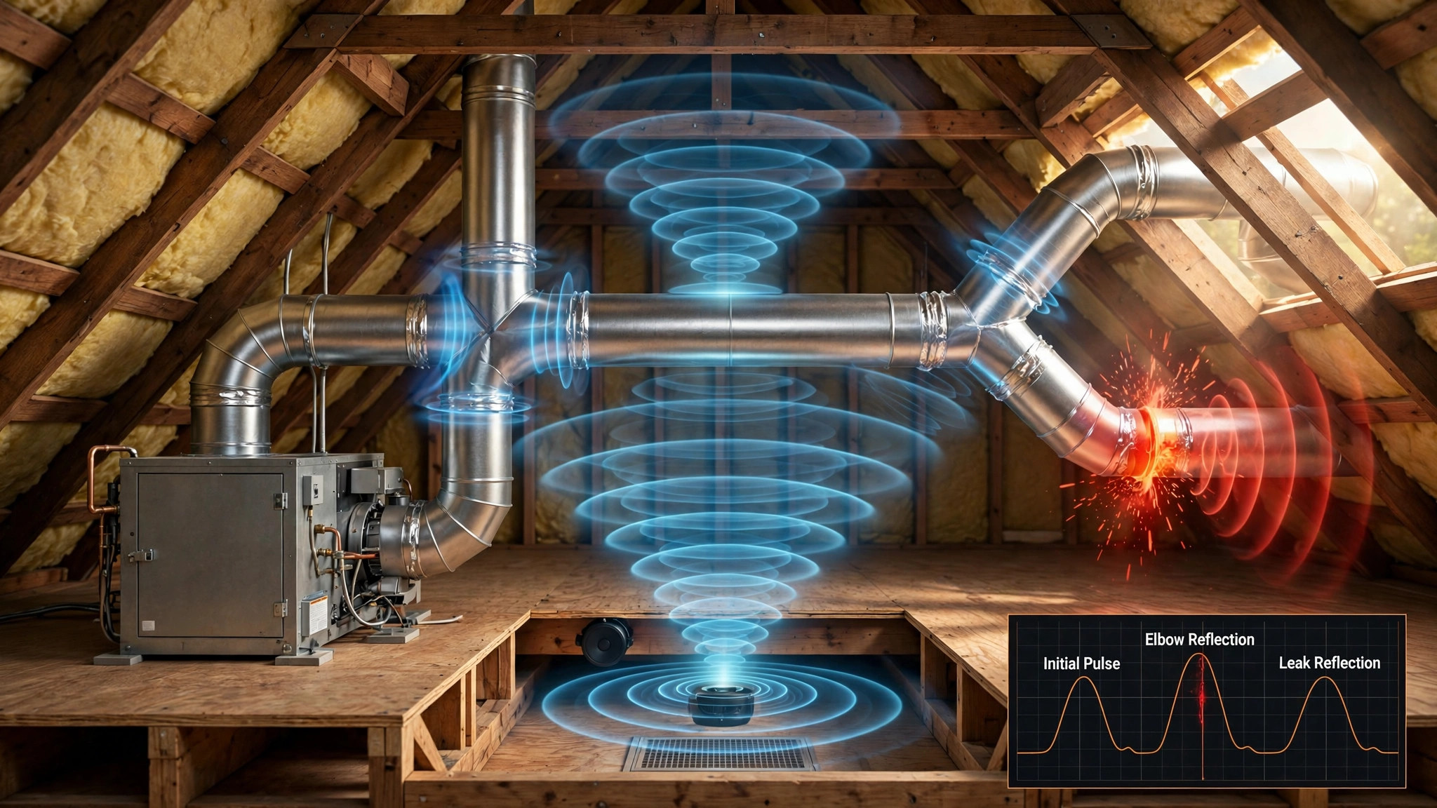
Disclosed is a system and method for localizing air leakage sites in residential HVAC ductwork without opening walls or crawling attics, using controlled acoustic pulse reflectometry. A speaker injects a swept-sine or maximum-length-sequence acoustic probe (100 Hz to 12 kHz) into the duct network with the HVAC system off. One or more MEMS microphones record the duct impulse response. Every impedance discontinuity in the duct reflects part of the probe; time-of-flight of each reflection gives its distance from the injection point. The core problem is that a duct network is full of legitimate reflections from elbows, takeoffs, dampers, and terminal boots. A machine-learned classifier, trained on labeled impulse responses from a duct mockup containing both structural fittings and controlled leaks, separates leakage reflections (holes, gap joints, disconnected sections) from structural ones. Each leak is then sized from its reflection coefficient, converted to an estimated airflow loss in CFM at operating static pressure, and ranked by energy impact. The output is a distance-ordered leak report that tells a contractor or homeowner exactly which joint to seal, closing the gap left by whole-duct leakage tests that report only a single total number.
Field of the Invention
This invention relates to building diagnostics and HVAC energy efficiency, specifically to non-intrusive localization of air leakage sites in forced-air ductwork through in-duct acoustic reflectometry and automated classification of reflection sources.
Background
Duct leakage is one of the largest hidden energy losses in residential buildings. ENERGY STAR estimates that about 20 to 30 percent of the air that moves through a typical home's duct system is lost through leaks, holes, and poorly connected ducts (ENERGY STAR: Duct Sealing). Leaked supply air never reaches the rooms it was conditioned for, and leaks in the return side pull unconditioned, often contaminated air from attics, crawlspaces, and garages into the living space, degrading both efficiency and indoor air quality.
The industry's standard diagnostic is the duct leakage test performed with a calibrated fan such as the Minneapolis Duct Blaster, which pressurizes or depressurizes the duct system and reports total leakage as CFM at 25 Pascals (CFM25) (Building America Solution Center: Total Duct Leakage Tests). This is a single aggregate number. It tells a homeowner their ducts leak 180 CFM but not whether that loss comes from one disconnected trunk joint in the attic or fifty pinhole gaps spread across twenty registers. Finding the actual sites requires a technician to crawl the attic or crawlspace with a flashlight, visually inspecting every joint, often in 120°F heat, often in spaces too tight to reach. Many joints are buried under insulation or inside wall cavities and are never found.
Aerosol duct sealing services (e.g., Aeroseal) address leakage from inside the duct but have their own blind spot: they report a before-and-after aggregate number, and their process cannot seal fully disconnected joints (gaps above a few millimeters remain open), so the technician still needs to know where the large defects are before the aerosol run. The economic consequence is concrete: a disconnected trunk joint can waste several hundred dollars of energy per year and defeat an entire aerosol sealing job.
Handheld ultrasonic leak detectors take a passive approach: they listen for the high-frequency hiss of air escaping while the system runs. They cannot quantify a leak, they miss leaks that only manifest under static conditions, and they give no principled distance estimate. What does not exist is an active method that probes the duct with a known signal, measures the response, and computes where each defect sits.
Acoustic reflectometry is a mature technique in adjacent domains but has never been applied to HVAC air ducts. Acoustic pulse reflectometry has been used to map the internal profile of wind instruments: an acoustic pulse is sent into the tube, the reflected sound is recorded with a microphone, and the complete bore profile is calculated from the heights of the reflection peaks and the time intervals between them, resolving leadpipe defects with 0.03 mm accuracy (J. Buick et al., Measurement Science and Technology 13, 750 (2002), reported in Physics World). The same principle has been applied in medicine to study the windpipe. Researchers have likewise demonstrated acoustic time-domain reflectometry for fault detection in water-distribution pipelines, where an injected pulse's reflections locate blockages and leaks.
The gap in the art is twofold. First, no reference applies controlled acoustic reflectometry to sheet-metal air ductwork to locate leakage. The acoustic environment of a duct network is far more cluttered than a pipe or an instrument bore: every elbow, takeoff, damper, and boot produces a legitimate reflection, and no prior work separates those from leak reflections. Second, no reference teaches an automated, learned classifier that distinguishes leakage reflections from structural reflections in duct impulse responses, nor a method for sizing a leak from its reflection signature and ranking detected leaks by energy impact. The claimed invention is the first complete in-duct leakage localization system for residential HVAC.
Detailed Description
1. System Architecture
The preferred embodiment comprises: (a) an acoustic source module containing a compact full-range driver (2 to 4 inch, flat response 80 Hz to 15 kHz) in a sealed enclosure with a soft gasket that seats into a removed register grille or into the supply plenum access panel; (b) one or more sensing nodes, each a MEMS microphone (e.g., Knowles SPH0645LM4H or equivalent, flat 50 Hz to 15 kHz, SNR 65 dB) with a microcontroller, positioned at two or more registers; (c) a controller, implemented as a tablet or smartphone application, that generates the probe signal, synchronizes source and sensors, computes the impulse response, runs classification and localization, and renders the leak report; and (d) optional wireless sensor modules using BLE 5.0 that clip into register grilles and pair with the controller. Target cost for the contractor kit: $150 to $300 in parts.
The measurement is performed with the HVAC system off and the duct network at rest. All registers except the injection point are sealed with magnetic register covers during the scan, so the measured reflections originate from inside the network rather than from open grilles. An ambient noise floor check rejects measurements taken above 55 dBA background.
2. Probe Signal and Impulse Response Acquisition
The probe is a logarithmic swept sine, 100 Hz to 12 kHz, duration 2 seconds, or equivalently a maximum-length sequence (MLS) of order 16 (65,535 samples) at 48 kHz sampling. Sound pressure level at the injection point is 75 to 85 dBA, loud enough for a clean measurement but quiet enough for occupied homes and below levels that would disturb pets or sleeping occupants. Eight to sixteen excitations are averaged coherently to suppress uncorrelated noise.
The duct impulse response is obtained by deconvolving the recorded signal with the known probe (swept-sine) or by Hadamard transform (MLS). Each sample of the impulse response at time t corresponds to a reflector at distance d = c·t/2 from the injection point, where c is the speed of sound corrected for duct air temperature: c = 331.3 + 0.606·T, with T in °C measured by the controller or a sensor on the source module. With 11.9 kHz of usable bandwidth, the theoretical range resolution is c/(2B) ≈ 1.4 cm; after peak fitting, practical localization accuracy is approximately ±0.15 m for isolated reflections. Reflections arriving later than 2·L_max/c (where L_max is the longest duct run entered into the layout model) are discarded as multiple-bounce artifacts.
3. Duct Layout Model
The controller holds a duct layout model built in one of two ways. In the manual mode, the homeowner or technician enters the register count, the approximate length of each run, and fitting types through a guided app interface; this takes roughly five minutes for a typical home. In the automatic mode, the system injects at two or more registers and uses two-way time-of-flight constraints to reconstruct the duct tree: a reflection observed from injection point A at time t_A and from injection point B at time t_B lies on the tree at positions satisfying the round-trip distances, and graph search over the tree resolves branch assignments. The layout model generates predicted arrival times for structural reflections, which serve as priors for the classifier.
4. Reflection Detection and Feature Extraction
Reflections are detected by peak picking on the envelope of the impulse response after subtracting a learned noise floor. For each detected reflection the system extracts a feature vector: (a) normalized peak amplitude relative to the incident pulse; (b) arrival time; (c) −3 dB temporal width; (d) spectral centroid of the reflected wavelet; (e) phase-slope linearity across the band (group delay deviation), which distinguishes the sharp all-pass-like phase of a hard obstruction from the dispersive phase of a compliant leak; (f) late-tail decay rate over the 20 ms following the peak, since a leak sustains radiated energy while a hard fitting produces a compact return; and (g) deviation from the sealed-state baseline impulse response at the same arrival time, where a baseline exists.
5. Machine-Learned Reflection Classification
A gradient-boosted decision tree ensemble (or equivalently a one-dimensional convolutional neural network over the reflection wavelet) classifies each reflection as structural or leakage, and leakage reflections are sub-typed as hole, gap joint, or full disconnection. The classifier is trained on a labeled dataset of several thousand impulse responses collected from a controlled duct mockup containing: rigid round sheet-metal duct in 6, 8, and 10 inch diameters; flexible insulated duct runs; 90-degree elbows; takeoffs; balancing dampers set at 0, 30, 60, and 90 degrees; terminal boots; and controlled leaks including drilled holes of 3, 6, 12, and 25 mm, gap joints of 2, 5, and 10 mm, and fully disconnected joints. Data augmentation includes temperature-shifted resampling (±15 °C) and noise injection at realistic SNRs. On held-out mockup data the classifier targets better than 90% precision and recall on the leak class; in the field, classification confidence below 0.6 is reported as "uncertain, inspect visually" rather than forced into a class.
6. Leak Sizing and Energy Ranking
The reflection coefficient R of a classified leak, defined as the ratio of reflected to incident pressure amplitude in the 1 to 4 kHz band, maps to an effective orifice area through a calibration curve measured on the mockup. The orifice area is converted to airflow loss in CFM at the operating static pressure of the branch (default 0.5 inches water column for residential supply trunks, adjustable per measurement). Annual wasted energy is estimated as: CFM loss × runtime hours from thermostat history × 1.08 × |T_supply − T_zone| / system efficiency, where 1.08 is the standard sensible-heat constant for air in BTU/hr per CFM per °F. Each detected leak receives a priority score proportional to its estimated annual energy waste, and the report is sorted by this score so the largest defects, typically disconnected joints, appear first.
7. Multi-Injection Disambiguation
A single injection cannot distinguish a leak on a parallel branch from one at the same acoustic distance on another branch. The system therefore repeats the scan injecting from a second register, preferably on a different branch. A reflection that is a true leak produces consistent two-way time-of-flight pairs that triangulate to a single node on the duct tree graph; structural reflections that are branch-specific fail the consistency test. The tree-graph solver performs a best-first search over candidate nodes, minimizing the squared residual of observed versus predicted arrival times across all injections.
8. Output Report and Contractor Handoff
The report lists each classified leak with: distance from the injection register (e.g., "4.2 m along the branch toward the master bedroom register"), estimated effective leak area, estimated CFM loss, annual energy waste in kWh and dollars at the local utility rate, classification confidence, and a repair priority rank. A simplified floor-plan sketch annotated with the leak positions is generated from the layout model. The report exports as PDF for handoff to a sealing contractor and includes a machine-readable JSON record of every reflection with its features and classification.
9. Post-Sealing Verification
After sealing work, the scan is repeated. The difference in total reflection energy in the leak class between the two scans quantifies the improvement independently of any aggregate leakage test. The system supports before-and-after pairing with a Duct Blaster measurement: the Blaster provides the authoritative total CFM25 number for code compliance, while the reflectometry scan provides the locations and the verification that each specific site was sealed.
10. Embodiments
- Contractor kit: battery-powered speaker module, two wireless microphone wands, and a tablet application. Scan time per home: 20 to 40 minutes. This is the primary commercial embodiment.
- DIY phone embodiment: a smartphone application that uses the phone speaker as the acoustic source (placed at a floor register) and the phone microphone as the sensor, with magnetic register covers mailed to the homeowner. Reduced bandwidth (phone speakers are usable to roughly 8 kHz) gives coarser localization, approximately ±0.3 m, which is sufficient to identify the room and branch.
- Integrated register module: a BLE-connected speaker-plus-microphone puck that clips into a standard 4×10 register grille, paired with the controller, enabling automated periodic re-scans after duct cleaning or renovation.
- Return-side embodiment: the same method applied to return ductwork, which is often more leaky and draws unconditioned air from attics and crawlspaces; leaks on the return side are classified and reported with an indoor-air-quality flag in addition to the energy rank.
11. Figures Description
- Figure 1: System block diagram showing the source module at a supply register, wireless microphone nodes at two additional registers, and the controller application, with the duct network represented as an acoustic tree.
- Figure 2: Example impulse response with annotated reflections: incident pulse, elbow reflection at 1.8 m, takeoff reflection at 3.1 m, and a leak reflection at 4.2 m with its dispersive phase signature.
- Figure 3: Feature-space illustration separating structural and leakage reflections, showing the decision boundary of the trained classifier on the amplitude-versus-tail-decay plane.
- Figure 4: Triangulation geometry for two-injection disambiguation on a branched duct tree, with consistent time-of-flight pairs converging on a single leak node.
- Figure 5: Example ranked leak report with floor-plan sketch, per-leak distances, estimated CFM losses, and energy-waste priority scores.
Claims
- A system for localizing air leakage sites in HVAC ductwork, comprising: an acoustic source module configured to inject a controlled broadband acoustic probe into a duct network while the HVAC system is off; at least one acoustic sensing node configured to record the duct impulse response; and a controller configured to detect reflections in the impulse response, compute each reflection's distance from the source by time-of-flight, and classify each reflection as a structural reflection or a leakage reflection using a machine-learned classifier.
- The system of claim 1, wherein the acoustic probe is a logarithmic swept sine from 100 Hz to 12 kHz or a maximum-length sequence, and the impulse response is obtained by deconvolution or Hadamard transform, with coherent averaging of at least eight excitations.
- The system of claim 1, wherein the machine-learned classifier is trained on labeled impulse responses from a controlled duct mockup containing structural fittings and controlled leaks, and classifies each reflection using features comprising normalized amplitude, arrival time, temporal width, spectral centroid, group-delay linearity, late-tail decay rate, and deviation from a sealed-state baseline.
- The system of claim 1, wherein the controller further estimates an effective orifice area for each classified leak from its reflection coefficient via a calibration curve, converts the orifice area to an airflow loss in CFM at operating static pressure, and computes an annual energy waste estimate using HVAC runtime data.
- The system of claim 4, wherein the controller generates a ranked leak report sorted by estimated annual energy waste, listing for each leak its distance from the injection point, estimated CFM loss, classification confidence, and a repair priority.
- The system of claim 1, further comprising a duct layout model that predicts arrival times of structural reflections from elbows, takeoffs, dampers, and terminal boots, wherein the classifier uses the predicted arrival times as priors.
- The system of claim 1, further comprising multi-injection disambiguation, wherein the probe is injected from two or more registers and a tree-graph solver triangulates each leakage reflection to a single node of the duct network using two-way time-of-flight constraints.
- The system of claim 1, further comprising a sealed-state baseline impulse response, wherein subsequent measurements are differenced against the baseline to detect newly developed or degraded joints.
- The system of claim 1, wherein the acoustic source module and sensing node are implemented in a smartphone application using the phone speaker and microphone, with magnetic register covers sealing non-injection registers during the scan.
- A method for verifying duct sealing work, comprising: injecting a controlled broadband acoustic probe into a duct network before sealing work and recording a first duct impulse response; classifying reflections in the first impulse response as structural reflections or leakage reflections using a machine-learned classifier; repeating the injection and classification after the sealing work to obtain a second duct impulse response; and quantifying the sealing improvement as the reduction in total reflection energy assigned to the leakage class between the first and second impulse responses, independent of any aggregate duct leakage measurement.
Implementation Notes
Flexible insulated duct attenuates high frequencies strongly, roughly 3 to 6 dB per meter above 4 kHz in typical R-6 flex. The method therefore performs best on rigid sheet-metal trunk lines with short flex branch runs, which matches the majority of residential supply networks. Where a run is entirely long flex duct, the controller automatically restricts the analysis band to 100 Hz through 2 kHz and widens the reported localization tolerance.
The scan requires the HVAC system to be off; residual blower spin-down must be complete, which the controller verifies by checking the pre-scan noise floor against the 55 dBA threshold. Homes with open floor plans may show late-arriving reflections through open interior doorways; the layout model flags arrival times beyond 2·L_max/c for manual review.
Sound pressure levels of 75 to 85 dBA at the injection point fall within OSHA permissible exposure for the scan duration, and the controller enforces a cumulative daily exposure limit across repeated scans. The DIY embodiment displays a hearing-safety notice before the first excitation.
Calibration of the sizing curve should be repeated for each probe speaker model, since driver frequency response shapes the incident pulse and therefore the measured reflection coefficient. The contractor kit ships with a factory-measured calibration for its included speaker; the DIY embodiment performs an in-app loopback calibration by recording the phone's own speaker at a fixed distance.
Prior Art References
- ENERGY STAR: Duct Sealing: 20 to 30 percent of conditioned air lost through duct leaks
- Building America Solution Center: Total Duct Leakage Tests: Calibrated-fan duct testing (Minneapolis Duct Blaster), CFM25 aggregate measurement
- Aeroseal: Aerosol-based duct sealing from inside the ductwork
- Physics World: Acoustics map out the brass section: J. Buick et al., Meas. Sci. Technol. 13, 750 (2002): acoustic pulse reflectometry mapping wind-instrument bore profiles from reflection peaks and arrival times; also applied in medicine to the windpipe
- Knowles SPH0645LM4H: MEMS microphone datasheet