System and Method for Estimating Chimney Creosote Accumulation from Burn-Event Flue Temperature Profiles with Deposition Modeling and Creosote Stage Classification
A design disclosure: what a flue temperature probe could tell you about creosote, if somebody built the model. No prototype exists yet.
Abstract
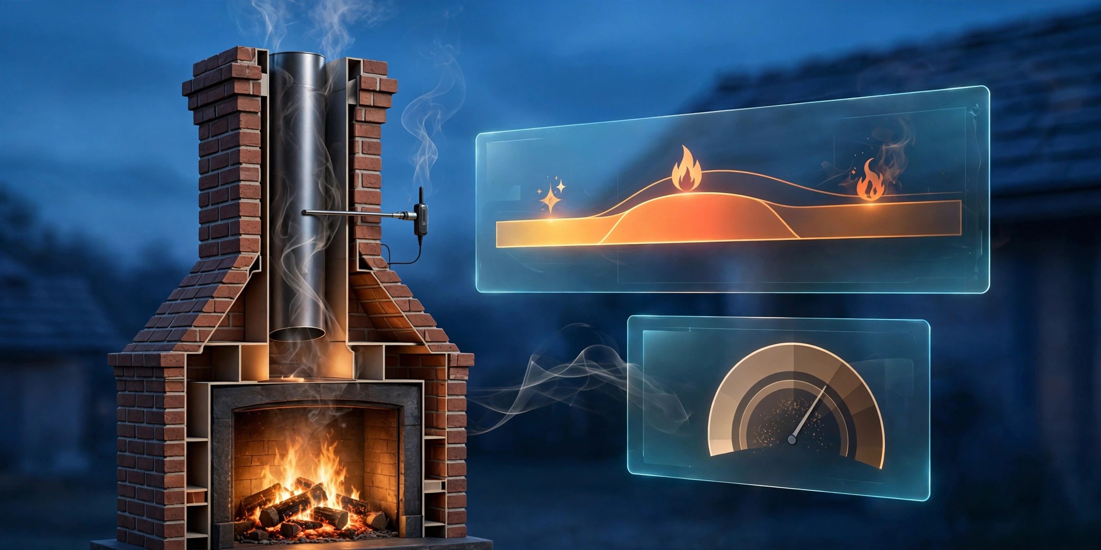
Creosote is the exhaust of your own fire, condensed onto your flue walls. Nobody can see it accumulating, so sweeping schedules run on the calendar instead of on the actual deposits, and the fires that need sweeping most urgently are the ones whose owners feel least urgency. This disclosure describes a way to track accumulation burn by burn: a temperature probe in the flue gas stream records each fire's temperature profile, software segments the burn into ignition, flaming, and smolder phases, and a deposition model converts each phase into an estimated creosote deposit, weighted by the burn's temperature regime, inferred fuel moisture, and flue-wall cooling conditions. Out of the model comes a running estimate of deposit thickness in equivalent millimeters against the NFPA 211 cleaning threshold of 1/8 inch (about two credit cards stacked), plus a stage classification that distinguishes brushable soot from the glazed deposits that require professional removal.
Disclosed is a system and method for estimating chimney creosote accumulation in solid-fuel heating appliances using a flue gas temperature probe, per-burn event segmentation, and a physics-informed deposition model. A thermocouple probe mounted in the connector pipe or flue gas stream samples flue gas temperature at one-second intervals during appliance operation. A burn-event segmenter detects fire start and end from temperature rise and decay signatures and classifies each burn into ignition, flaming, and smolder phases from the temperature profile and its time derivative, optionally fused with acoustic crackle-band energy from a MEMS microphone. A deposition model integrates per-phase deposition rates that scale with the time the flue gas temperature spends below the creosote condensation temperature (approximately 121 °C / 250 °F, design parameter), a smoke-density proxy derived from burn phase, and an inferred fuel-moisture multiplier estimated from the ignition-to-flaming transition duration. A flue-wall cooling correction derived from outdoor temperature adjusts for the cooler upper flue. A stage classifier tracks the weighted accumulation of Stage 1 (sooty), Stage 2 (tar flake), and Stage 3 (glazed) deposits. A glaze-migration term models how repeated hot burns bake earlier deposits toward higher stages. A threshold advisory module compares the equivalent deposit thickness against the NFPA 211 cleaning criterion of 1/8 inch (3.175 mm) and issues tiered sweep advisories, triggering a sweep-now advisory whenever glazed deposits are suspected regardless of thickness. A per-burn feedback report scores each fire on its fraction of clean flaming time and provides behavioral coaching on air control and fuel seasoning.
Technical Field
This disclosure relates to residential fire safety, specifically to estimation of creosote deposition in solid-fuel heating appliance chimneys (cf. IPC F23J 15/00, treatment of combustion products; IPC G01N 25/00, investigating materials by thermal means) by means of flue gas temperature sensing, burn-event modeling, and deposit stage classification.
Background
US fire departments answer an annual average of 38,881 home heating fires, 46 percent of them between December and February, and failure to clean is a factor in about 68 percent of fires involving a fireplace, chimney, or connector (NFPA heating-fire data, as compiled in an industry explainer). Creosote is not dirt blown up from the grate. It is the fire's own exhaust — smoke, water vapor, unburned wood particles, tar fog — condensed onto the cool inner wall of the flue, the way a hot shower fogs a cold mirror (High's Chimney Service). It is highly combustible, commonly cited as igniting around 451 °F, while flue gases routinely run hotter; creosote-fueled chimney fires can reach 2,000 °F, hot enough to crack a liner and spread fire into the structure.
Creosote comes in three industry-recognized stages. Stage 1 is dusty soot, roughly a third combustible, that brushes off. Stage 2 is hard brittle tar flake, roughly 60 percent combustible, a removal job rather than a cleaning job. Stage 3 is glaze, fused to the flue wall and described by industry sources as roughly 85 percent combustible: not residue, a fuel liner (High's Chimney Service; industry explainer). NFPA 211 puts the cleaning line at 1/8 of an inch of accumulation anywhere in the flue, or any glazed deposits at all. Appliance manuals uniformly instruct inspection every two months during the heating season and note that slow, smoldering burns produce the most creosote, with cooler surfaces accumulating deposits faster, which is why chimneys should be checked from both the top and the bottom (Heatilator Constitution C40 manual).
Existing sensing approaches do not model accumulation. US4486743A (Honeywell, 1984, "Creosote buildup detector and annunciator") discloses a detector that annunciates the presence of buildup; it detects an already-formed deposit rather than modeling the rate at which burns deposit it, and it provides no stage classification. US20110017197A1 discloses fireplace installation monitoring with temperature sensors that warn when temperature thresholds are exceeded; it is an overheat warning system, not a deposition model. WO2021051038A1 discloses sensor-based monitoring of solid fuel burning devices for emissions reduction and efficiency; its purpose is combustion optimization, not creosote accounting. A hobbyist build, the Chimney Sentinel project, alarms when flue temperature lingers in a danger zone: a threshold alert with no per-burn accounting and no stage concept.
Related disclosure LITF-PA-2026-145 discloses acoustic resonance spectroscopy and differential pressure sensing to detect obstructions in flues, including gradual creosote accumulation as one obstruction type. That disclosure detects deposits after they have narrowed the flue enough to shift its acoustic modes; it does not predict accumulation from burn physics, does not classify creosote stages, and does not model glaze migration from repeated hot burns. What the art lacks is a complete predictive system that: (a) attributes a deposit estimate to every individual burn from its measured temperature profile; (b) infers fuel moisture from burn dynamics rather than requiring a moisture meter; (c) classifies deposits into the industry's three creosote stages and models stage migration; and (d) converts the accumulation estimate into NFPA 211 threshold advisories plus per-burn behavioral feedback that reduces future deposition.
Obviousness deserves a direct answer here. Thermocouples in flues are old, and the correlation between cool burning and creosote is textbook. What is not obvious is the specific predictive combination disclosed here: phase-segmented deposition modeling in which each burn's ignition, flaming, and smolder intervals carry different deposition weights; fuel-moisture inference from the ignition ramp rather than a separate sensor; a flue-wall cooling correction from outdoor temperature that accounts for the documented top-of-chimney deposition bias; and a stage-migration model in which hot burns bake earlier soot toward glaze. A thermometer that alarms at high temperature does not do any of this, and a detector that sees existing buildup cannot tell you which of your last twenty fires caused it. The contribution is the burn-by-burn accounting ledger, not the probe.
Detailed Description
1. Sensor Probe and Installation
The sensor module comprises a K-type thermocouple probe (design parameter: rated to 1,000 °C continuous) inserted into the flue gas stream through a compression fitting in the connector pipe, nominally 45 cm (18 inches) above the appliance collar, oriented with the thermocouple junction centered in the gas stream. A second thermistor measures ambient temperature at the module housing. An optional MEMS microphone captures acoustic energy in the 2 to 8 kHz crackle band (design parameter) as a burn-phase auxiliary signal. Outdoor temperature is obtained from a local weather API or a paired outdoor sensor. The module samples temperature at 1 Hz (design parameter) and transmits via a low-power radio to a hub or directly to the user's phone; a CR123A lithium cell provides multi-season operation at one measurement cycle per burn, or the module may be USB-powered.
Placement in the connector pipe is deliberate. The connector is the hottest accessible point in the gas path and the easiest to instrument without chimney-top access; its temperature is a reliable proxy for the combustion regime even though deposition itself peaks higher up where the flue wall is cooler, which is what the cooling correction in Section 4 accounts for. The probe must not obstruct the flue: the junction sits at the pipe centerline with a profiled sheath under 8 mm diameter (design parameter), presenting negligible flow blockage in a 150 mm or larger connector.
2. Burn Event Segmentation and Phase Classification
A burn event is detected when the flue gas temperature rises more than 5 °C per minute sustained over three minutes (design parameter), or when the gas temperature exceeds ambient by 60 °C (design parameter), whichever occurs first. The event ends when the gas temperature decays to within 15 °C of ambient (design parameter). Each event is segmented into three phases from the temperature profile and its time derivative. The ignition phase runs from event start until the first sustained 260 °C (500 °F) crossing, including a ramp sub-phase while temperature rises through 150 to 260 °C (design parameters). The flaming phase is sustained gas temperature above 260 °C. The smolder phase is temperature below 260 °C on a falling slope or during slow decay, which closes the band between the ignition ramp and flaming onset so no burn interval goes unassigned. Re-stoking events, in which temperature re-rises above 260 °C after a smolder interval within the same overall event, are labeled as refuel transitions and re-enter the flaming phase.
The optional acoustic signal resolves an ambiguity that temperature alone cannot: a dying fire and a dampered-down fire can show similar temperatures, but the dampered fire crackles less. Crackle-band acoustic energy above a design threshold during a sub-150 °C interval biases the phase classifier toward smolder rather than post-burn cooling. When the microphone is absent, the classifier uses temperature dynamics alone and marks phase labels with reduced confidence, which propagates into the deposition uncertainty in Section 5 rather than silently degrading the estimate.
3. Fuel Moisture Inference
Wet wood is the largest controllable driver of creosote deposition: it burns cool, smolders long, and floods the flue with water vapor that carries tar to the walls. Requiring the user to probe every log with a moisture meter guarantees the data never gets entered. The system instead infers fuel moisture from burn dynamics. The ignition-to-flaming transition duration, the time from event start to the first sustained 260 °C crossing, is the primary feature: seasoned wood under 20 percent moisture content typically reaches flaming in minutes, while wet wood lingers in a cool, steamy ignition phase. The classifier maps the transition duration and the ignition-phase peak temperature into three fuel bands: seasoned (below 20 percent), marginal (20 to 25 percent), and wet (above 25 percent), all design-parameter thresholds calibrated against published drying curves. The fuel band multiplies the deposition rate: wet fuel carries a deposition multiplier of approximately 3 relative to seasoned fuel, and marginal fuel approximately 1.5 (design parameters, unvalidated).
This inference is statistical, not metrological. A small kindling fire and a large wet-log fire can produce similar ramp profiles at different absolute temperatures, so the classifier normalizes ramp duration against the event's eventual flaming-phase temperature. Persistent misclassification is bounded by design: the fuel band feeds the deposition rate as a multiplier, so even a fully wrong band assignment changes a single burn's contribution by a factor of three at most, and the threshold advisories in Section 6 operate on cumulative thickness with tiered margins that absorb per-burn error.
4. Deposition Rate Model
Creosote condenses when flue gas temperature at the wall falls below the condensation temperature, taken as 121 °C (250 °F, design parameter). The per-minute deposition rate during a burn is modeled as the product of three terms: a phase weight, a condensation factor, and the fuel multiplier. Phase weights reflect the smoke-density proxy of each phase: ignition 1.0, smolder 0.7 (design parameters, unvalidated), encoding the textbook observation that cool smoky burns deposit creosote while hot clean burns deposit almost none. The flaming phase carries no deposition weight: with flue gas temperature above the condensation temperature, the condensation factor is zero by construction, so hot clean burns contribute nothing to the deposition integral. Flaming burns still act on the stage accumulators through the glaze migration term in Section 5. The condensation factor is max(0, (T_cond − T_gas) / T_cond), so time spent far below the condensation temperature deposits proportionally more than time near it. The fuel multiplier from Section 3 scales the whole rate.
A flue-wall cooling correction accounts for the documented top-of-chimney deposition bias: cooler surfaces accumulate deposits faster, and the upper flue runs cooler when outdoor air is cold. The correction scales the condensation factor by (1 + k · max(0, T_ref − T_outdoor) / T_ref) with T_ref = 10 °C and k = 0.5 (design parameters, unvalidated), so a midwinter burn at −10 °C deposits roughly twice the baseline rate of the same burn profile in mild weather. This is the term that explains why the first cold-night fire of the season, in a chimney that sat all summer, is disproportionately dangerous: the model attributes it correctly to wall cooling, not to burn behavior.
Per-burn deposit is the time integral of the deposition rate over the event, converted from the model's arbitrary rate units to equivalent deposit thickness in millimeters using the user-entered flue diameter and effective flue length at commissioning, divided into the estimated deposit mass proxy. The conversion constant is a design parameter and the dominant source of absolute-thickness uncertainty; the system's advisories therefore use both the absolute NFPA 211 threshold and a relative tier on cumulative model units, so a miscalibrated conversion constant shifts the absolute tier without disabling the relative one.
5. Creosote Stage Classification and Glaze Migration
Thickness alone does not determine hazard: 1/8 inch of Stage 1 soot and a glaze of Stage 3 are different emergencies, and NFPA 211 requires cleaning for any glaze regardless of thickness. The stage classifier maintains three parallel accumulators. Deposits formed during predominantly flaming burns, with brief ignition phases and seasoned fuel, accrue to the Stage 1 accumulator. Deposits formed during long smolder and ignition phases, or with marginal or wet fuel, accrue to the Stage 2 accumulator. The Stage 3 accumulator is fed by glaze migration: when a burn's flaming phase sustains gas temperature above 315 °C (600 °F, design parameter) for more than 30 minutes (design parameter), a fraction of the Stage 1 and Stage 2 accumulators migrates to Stage 3, modeling the baking process by which repeated hot fires fuse earlier deposits into glaze. This captures the counterintuitive hazard that the "good hot burns" a conscientious owner runs can convert last month's soot into this month's glaze.
The stage classification drives the advisory logic in Section 6 and the feedback in Section 7. A chimney whose accumulator is dominated by Stage 1 after a season of hot, clean burns receives a routine-schedule advisory; a chimney whose Stage 3 accumulator crosses its design threshold triggers the sweep-now advisory even when total equivalent thickness is well below 1/8 inch, directly implementing the NFPA 211 any-glaze rule. The stage accumulators reset on a logged sweep event, entered by the user or by a connected sweep service, with a commissioning default that assumes unknown prior history and therefore starts the Stage 2 accumulator at a conservative non-zero seed (design parameter).
6. Accumulation Index and Sweep Thresholds
The running accumulation index is the sum of per-burn equivalent thickness since the last logged sweep, presented in millimeters alongside the NFPA 211 cleaning line at 3.175 mm (1/8 inch, about two credit cards stacked). Advisory tiers are: Tier 1, routine, index below 1.6 mm (half the cleaning line, design parameter); Tier 2, schedule sweeping, index from 1.6 mm to 3.175 mm or Stage 2 dominant; Tier 3, sweep before the next fire, index at or above 3.175 mm or Stage 3 accumulator above its design threshold. Boundary values belong to the higher tier. All thresholds are design parameters, not validated safety criteria, and the advisory display states explicitly that the index is a model estimate, that physical inspection remains the authority, and that the system does not certify a chimney as safe to burn.
The tier display includes a burn-count projection: given the owner's recent per-burn average deposit rate, the system estimates how many more typical burns remain before the next tier, turning an abstract millimeter number into a concrete "about six more fires like last Saturday's" (design presentation, unvalidated). After a logged sweep, the index and stage accumulators reset and the projection restarts, so the system also functions as a sweep-interval optimizer: owners who burn hot and clean will see long intervals, and owners who smolder will see short ones, which is exactly the incentive structure the physics demands.
7. Per-Burn Feedback and Behavioral Coaching
Each completed burn produces a burn report: phase breakdown with durations, estimated fuel band, per-burn deposit contribution in model units and equivalent micrometers, and a burn score defined as the fraction of the event spent in the flaming phase weighted by the fuel band (design metric, unvalidated). The report includes behavioral coaching tied to the measured profile: a long ignition phase prompts advice to use drier kindling and smaller splits at startup; a dominant smolder phase prompts advice to open the air control and avoid overnight dampering; a wet fuel band prompts advice on wood storage and seasoning time. The coaching references the owner's own burn history ("your last five Saturday fires averaged a 22-minute ignition phase; seasoned wood would cut that roughly in half") rather than generic tips.
This feedback loop is the system's second safety mechanism after the threshold advisories. Creosote deposition is overwhelmingly a behavior problem: the same chimney with the same wood produces an order of magnitude less deposit under hot clean burning than under smoldering. A model that only counts deposits without changing burns is a countdown timer; a model that shows the owner which habit each deposit came from is a prevention tool. The burn score gamification is deliberately modest, a single number per burn with a seasonal trend, because the goal is a cleaner flue, not a leaderboard.
8. Prospective Figures Description
No figures are rendered in this disclosure; the descriptions below specify what an implementing embodiment would depict.
- Figure 1 (illustrative): Sensor module installation showing the thermocouple probe inserted through a compression fitting into the connector pipe 45 cm above the appliance collar, module housing with ambient thermistor and optional microphone, and wireless link to the hub.
- Figure 2 (illustrative): Example burn-event temperature profile annotated with ignition, flaming, and smolder phase boundaries, the 121 °C condensation line, and the per-minute deposition rate curve underneath.
- Figure 3: Example (illustrative): seasonal accumulation chart showing the running thickness index against the 3.175 mm NFPA 211 line, the three stage accumulators as stacked areas, and tier advisory bands.
- Figure 4: Example (illustrative): per-burn report layout with phase breakdown, fuel band, deposit contribution, burn score, and coaching message.
Claims
- A system for estimating chimney creosote accumulation, comprising: a temperature probe configured to be mounted in the flue gas stream of a solid-fuel heating appliance connector pipe; a burn-event segmenter that detects burn start and end from flue gas temperature rise and decay signatures and classifies each burn into ignition, flaming, and smolder phases from the temperature profile and its time derivative; a deposition model that integrates a per-phase deposition rate over each burn, wherein the rate scales with the time the flue gas temperature spends below a creosote condensation temperature, a smoke-density proxy derived from burn phase, and an inferred fuel-moisture multiplier; and a threshold advisory module that accumulates per-burn deposit estimates into a running thickness index and issues tiered sweep advisories against a cleaning threshold.
- The system of claim 1, wherein the fuel-moisture multiplier is inferred from the duration of the ignition-to-flaming transition and the ignition-phase peak temperature, classifying fuel into seasoned, marginal, and wet bands without a dedicated moisture sensor.
- The system of claim 1, further comprising a flue-wall cooling correction that scales the deposition rate by outdoor temperature, increasing the estimated deposition for burns conducted in colder outdoor conditions to model the documented top-of-chimney deposition bias.
- The system of claim 1, further comprising a MEMS microphone, wherein crackle-band acoustic energy biases the phase classifier between smolder and post-burn cooling intervals, and wherein phase labels carry reduced confidence when the microphone is absent.
- The system of claim 1, further comprising a creosote stage classifier maintaining separate accumulators for Stage 1 sooty, Stage 2 tar flake, and Stage 3 glazed deposits, wherein the advisory module issues a sweep-now advisory when the glazed-deposit accumulator exceeds a design threshold regardless of total equivalent thickness.
- The system of claim 5, further comprising a glaze migration model wherein a flaming phase sustained above a design temperature for longer than a design duration transfers a fraction of the Stage 1 and Stage 2 accumulators into the Stage 3 accumulator, modeling the baking of earlier deposits into glaze by repeated hot burns.
- The system of claim 1, wherein the threshold advisory module presents the running thickness index against the NFPA 211 cleaning criterion of 1/8 inch (3.175 mm) and projects a remaining-burn count to the next advisory tier from the owner's recent per-burn average deposit rate.
- The system of claim 1, further comprising a per-burn feedback module that reports phase durations, the inferred fuel band, the per-burn deposit contribution, and a burn score defined as the flaming-phase fraction weighted by fuel band, with behavioral coaching messages tied to the measured burn profile.
- The system of claim 1, wherein the running thickness index and stage accumulators reset on a logged sweep event, and wherein the stage accumulators initialize with a conservative non-zero seed when prior sweep history is unknown.
- A method for estimating chimney creosote accumulation, comprising: sampling flue gas temperature at one-second intervals from a probe mounted in a solid-fuel heating appliance connector pipe; detecting burn events from temperature rise and decay signatures; segmenting each burn into ignition, flaming, and smolder phases from the temperature profile and its time derivative; inferring a fuel-moisture band from the ignition-to-flaming transition duration; computing a per-burn deposit estimate by integrating a deposition rate that scales with time below a creosote condensation temperature, a phase-derived smoke-density proxy, the fuel-moisture band, and an outdoor-temperature cooling correction; accumulating per-burn estimates into a running thickness index and stage-classified accumulators; and issuing tiered sweep advisories against the NFPA 211 1/8 inch cleaning criterion with a sweep-now advisory on suspected glazed deposits.
- The method of claim 10, further comprising generating a per-burn report with phase durations, inferred fuel band, deposit contribution, and a burn score, and providing behavioral coaching on air control and fuel seasoning derived from the measured burn profile.
Implementation Notes
Scope of this disclosure: This document is a design proposal. No prototype has been built and no field validation has been performed; all quantitative parameters in this disclosure (temperatures, durations, phase weights, multipliers, thresholds, and conversion constants) are untested design choices.
The model's weakest link is the mass-to-thickness conversion. A thermocouple measures temperature, not grams of tar, and the conversion from integrated rate units to millimeters of deposit rests on an assumed deposition efficiency and flue surface area. The design mitigates this two ways: the relative tier on cumulative model units operates independently of the absolute conversion, and the per-burn feedback uses model units directly, so coaching value survives even if the millimeter scale is off by a factor of two. The honest statement is that the system's millimeter numbers are estimates with wide error bars, and the tier boundaries are set conservatively to absorb that uncertainty.
Behavioral gaming is a foreseeable failure mode. An owner who learns that long ignition phases hurt the burn score could game the metric by pre-heating the probe area or starting fires with accelerants, which would improve the score while worsening real safety. The coaching explicitly warns against accelerants, and the fuel-moisture inference treats anomalously fast ramps with high ignition-phase temperatures as suspect rather than exemplary. More importantly, the system's safety advisories never relax based on burn scores: a good score earns coaching praise, never a longer sweep interval.
Probe fouling bounds long-term accuracy. The thermocouple sheath itself accumulates deposits, which insulates the junction and biases readings low over a heating season; a slow downward drift in peak flaming temperatures across burns with similar profiles flags fouling and prompts probe cleaning at the same visit as the chimney sweep. The design treats probe maintenance as part of the sweep workflow, not as a separate chore.
Multi-appliance and shared flues are out of scope for the base design. A fireplace and a wood stove sharing one flue produce interleaved temperature profiles the segmenter cannot attribute; the commissioning flow requires one monitored appliance per flue and refuses to produce an index for shared flues rather than attributing deposits to the wrong appliance. Pellet stoves, with their forced-draft steady combustion, produce flue temperature profiles outside the phase model's assumptions and are excluded from the supported appliance list.
All temperature and acoustic processing runs on the hub or phone. Raw one-second temperature series are retained locally for the burn history; only per-burn aggregates, phase statistics, and the accumulation index leave the device, and then only for backup or the user's own multi-device access. No audio is stored: the microphone contributes only crackle-band energy features computed on the device.
Prior Art References
- NFPA 211, Standard for Chimneys, Fireplaces, Vents, and Solid Fuel-Burning Appliances: 1/8 inch accumulation cleaning criterion; cleaning required for any glazed creosote deposits
- High's Chimney Service, "Why and How to Minimize Creosote Buildup in your Chimney": Creosote formation by condensation of combustion byproducts on cool flue walls; three stages (sooty, tar flake, glazed) with increasing combustibility
- US4486743A (Honeywell Inc., 1984): Creosote buildup detector and annunciator; detects presence of already-formed buildup, no deposition rate modeling or stage classification
- US20110017197A1: Method and system for monitoring a fireplace installation; temperature sensors with over-temperature warnings, no creosote accumulation modeling
- WO2021051038A1: Monitoring and controlling solid fuel burning devices to reduce emissions and improve efficiency; sensor-based combustion optimization, no creosote deposition accounting
- Chimney Sentinel (EDN project): Flue temperature probe with alarm on sustained danger-zone temperature; threshold alerting, no per-burn deposition model
- LITF-PA-2026-145: Flue obstruction detection via acoustic resonance spectroscopy and differential pressure; detects deposits after flue narrowing, distinct from predictive burn-physics deposition modeling