System and Method for Diagnosing Ceiling Fan Mechanical Imbalance, Bearing Degradation, and Mount Failure Risk Using Smartphone Camera-Based Optical Flow Wobble Analysis
Abstract
Ceiling fan wobble is treated as a cosmetic annoyance, but out-of-balance operation is a cited mechanism in fans falling from ceilings. Disclosed is a system and method for diagnosing the mechanical health of a residential ceiling fan using only a smartphone camera. The user holds the phone beneath the running fan and records a short video clip at each of two or more speed settings.
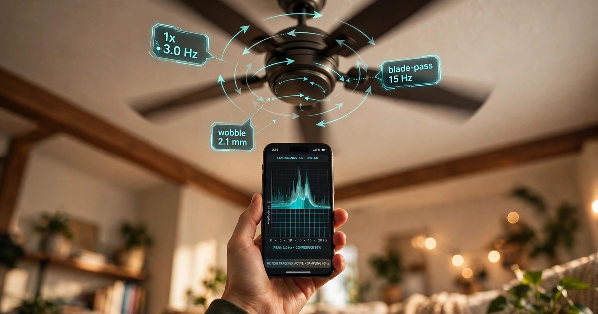
The app performs markerless dense optical-flow tracking of the motor housing and the blade-sweep region, extracting a displacement time series from which a frequency spectrum is computed. The spectrum is decomposed into physically meaningful components: the shaft-rotation frequency (1x), the blade-pass frequency (blade count times rotation frequency), a sub-rotational pendulum-sway mode of the downrod-mount assembly, and broadband bearing-wear energy. Pixel displacements are converted to millimeters using the fan's known diameter or AR depth data, producing a calibrated wobble amplitude.
By comparing the phase of peak motor-housing displacement against the blade-pass intensity reference, the system identifies which blade carries the excess mass and generates guided balancing instructions: which blade, where along the blade to place a counterweight, and how to iterate. A mount-failure risk score is computed from the pendulum-mode amplitude and its growth trend; when the score crosses a threshold, the app issues a stop-and-inspect alert. Longitudinal trending across sessions separates progressive bearing wear from static installation imbalance.
Field of the Invention
This invention relates to consumer appliance diagnostics, specifically to non-contact vibration analysis of rotating residential equipment using commodity smartphone cameras, computer vision, and spectral decomposition to identify imbalance, bearing degradation, and mounting failures.
Background
Ceiling fan wobble is treated as a cosmetic annoyance. It is also a mechanical symptom with a documented safety record. The U.S. Consumer Product Safety Commission has issued multiple recalls in which vibration and imbalance were implicated: Emerson Corsair fans were recalled because the hanger bracket could "spread apart due to heat from the motor and/or out-of-balance operation, causing the fan to fall from the ceiling" (US Recall News); Casablanca recalled 43 models (~30,000 units) after eight reports of motors and blades falling (Electrical Business); Kichler recalled 42,000 fans after 62 reports of blade arms breaking or detaching (Consumer Reports); and Youngo/Hampton Bay recalled 9,460 Halwin fans in August 2026 after blades separated from the flywheel (ConsumerAffairs). Out-of-balance operation is therefore not merely irritating; it is a cited mechanism in fans falling on people.
Existing homeowner remedies are entirely manual and qualitative. The standard procedure is the adhesive-weight balancing kit: clip a test weight to a blade, run the fan, judge wobble by eye, move the clip to the next blade, repeat. The judgment step is subjective, the phase relationship that determines which blade is actually heavy is never measured, and nothing in the process distinguishes a heavy blade from a loose downrod or a dying bearing. Dreo sells a kit bundling a laser level with a vibration sensor, but it requires dedicated hardware. A $2.99 app described in a user account on Medium asks the user to tape a marker dot to one blade and holds the camera under the spinning fan to analyze wobble, then overlays weight placement in AR. Industrial machinery has vibration analysis down to a science (ISO 10816 zone ratings; SKF's Enlight system pairs a Bluetooth vibration sensor with a phone app, The Fabricator), but every consumer ceiling-fan solution either requires contact sensors, stick-on markers, or trained judgment.
The gap in the art is a complete markerless system that: (a) measures wobble from video alone with no tape, markers, or attached sensors; (b) decomposes the motion into its physical sources, separating blade imbalance from mount sway and bearing wear; (c) calibrates pixel motion to millimeters so amplitudes are comparable across phones, distances, and sessions; (d) identifies the heavy blade by phase, not trial and error; and (e) converts the measurement into a mount-failure risk assessment with a stop-and-inspect alert, tying the diagnosis to the documented fall hazard.
A natural objection is that the phone already contains a vibration sensor, so the user could simply rest it on the fan. That approach fails on three counts. First, safety: resting anything on a spinning rotor, or on the housing of a wobbling fan, is a bad plan, and reaching the fan at all requires a ladder. Second, the interesting motion is multi-point: the diagnostic value comes from measuring the housing displacement, the blade-pass phase, and a motion-free reference simultaneously, which one contact point cannot provide. Third, contact coupling is uncontrolled: a phone resting on a blade introduces its own mass and rattling, while video measures the undisturbed system from a safe distance. The camera is not a worse accelerometer here; it is the only practical sensor for the measurement that matters.
Detailed Description
1. Capture protocol
The user stands or sits beneath the fan, holds the phone camera pointed at the fan, and records a 10-second clip at each of at least two speed settings (typically medium and high). The app auto-detects fan presence via a fan-shaped region detector (circular motor housing with radial blade edges) and confirms adequate framing: the motor housing must occupy at least 60 pixels of width for reliable tracking. If framing is poor, the app instructs the user to step closer or zoom.
Frame rate selection is driven by the physics being measured. A typical five-blade fan on high spins at 160-220 RPM (2.7-3.7 revolutions per second), giving a blade-pass frequency of 13-18 Hz. A 60 fps capture has a Nyquist limit of 30 Hz: enough to resolve the rotation frequency (1x) and the blade-pass fundamental cleanly, but not the first blade-pass harmonic, which reaches 27-37 Hz across the speed range. The app therefore prefers 120 or 240 fps slow-motion modes where available, which extend clean resolution to the blade-pass harmonics and the bearing-wear sidebands that live around them. The phone should be held as still as practical; residual hand shake occupies the 2-10 Hz band and is partially removed by a reference-patch subtraction step (Section 3).
2. Markerless multi-point tracking
No tape, dots, or markers are required. Two regions of interest (ROIs) are tracked:
- Motor-housing ROI: A circle detector locates the motor can. Dense optical flow (Farnebäck) or sparse Lucas-Kanade features on the housing edge track its in-plane position frame to frame. At a camera-below viewpoint, the housing's vertical image motion encodes the fan's axial/tilt wobble; lateral motion encodes sway. The tracked signal is a two-channel displacement time series, x(t) and y(t), in pixels.
- Blade-sweep annulus ROI: An annular region between the housing edge and the blade tips is monitored for periodic intensity flicker. At typical speeds, individual blades are motion-blurred, but each blade's passage modulates the annulus brightness at the blade-pass frequency. This flicker signal serves as a phase reference: it marks when a blade passes a fixed angular position, without needing to see any individual blade or marker.
A background reference patch (a ceiling region far from the fan) is tracked simultaneously. Its motion, which is dominated by hand shake, is subtracted from the housing signal after amplitude scaling, substantially suppressing camera-motion artifacts in the 2-10 Hz band. Dense optical flow routinely achieves sub-pixel displacement accuracy (0.1-0.3 px), which is what makes millimeter-scale amplitudes measurable at typical framing distances.
3. Spectral decomposition into physical sources
The displacement and flicker signals are windowed (Hann, 5-second segments, 50% overlap) and transformed via FFT. A peak picker identifies the rotation frequency f0 as the strongest sub-blade-pass peak in the housing spectrum, cross-checked against the flicker spectrum where blade-pass f_bp must equal N_blades times f0. The spectrum is then classified into bands:
- 1x (rotation frequency): Energy here indicates static imbalance: a single heavy spot on the rotor assembly, or an eccentric motor. The canonical blade-imbalance signature.
- Blade-pass (N x f0) and harmonics: Elevated blade-pass energy with modest 1x indicates aerodynamic or geometric asymmetry among blades (pitch mismatch, warped blade) rather than a single heavy mass.
- Sub-rotational pendulum mode (0.4-0.8 Hz): A downrod-mounted fan hangs as a physical pendulum; for a pivot-to-mass distance near 0.9 m the natural frequency is about 0.5 Hz. Whole-fan translation at this frequency, at an amplitude comparable to the 1x component, indicates a compliant mount: loose canopy screws, a loose downrod set screw, or a degraded ball-and-socket hanger. This is the mount-failure precursor band.
- Broadband high-frequency energy: Rising noise floor above the blade-pass harmonics up to the Nyquist limit, with sidebands around those harmonics, indicates bearing roughness. Bearings that once ran quietly develop broadband vibration as races pit. At 60 fps this band is useful only on the low end of the speed range; 120 or 240 fps capture is needed to resolve it fully.
Each band's RMS amplitude is reported in both pixels and calibrated millimeters (Section 4), with the 1x phase reported relative to the flicker reference.
4. Pixel-to-millimeter calibration
Amplitudes are meaningless across sessions unless calibrated. The app converts pixels to millimeters by one of three routes, in preference order: (a) AR depth (ARKit/ARCore plane distance) giving true scale at the fan's distance; (b) the user-entered fan diameter (most residential fans are 42, 44, 48, 52, or 60 inches; 52 inches = 1321 mm), where the blade-sweep diameter in pixels maps directly to millimeters; or (c) a perspective model assuming the blade plane is parallel to the image plane, with a stated uncertainty bound. Calibration source and uncertainty are recorded with every measurement so that trending comparisons only pair like with like.
5. Heavy-blade identification by phase
The key diagnostic step replaces the trial-and-error weight shuffle. The 1x housing displacement reaches its maximum when the heavy side of the rotor swings through the direction of the measured displacement. The flicker reference independently marks blade-passage instants. The phase offset between peak 1x displacement and the nearest blade-passage tick identifies which blade carried the heavy side through that position. With a five-blade fan, phase resolution of 72 degrees is enough to single out one blade; measured phases are quantized to the nearest blade index and a confidence is reported from the phase stability across windows.
The app then issues guided balancing instructions: the identified blade, a starting counterweight position (mid-blade, about 60% of the radius from the hub), and an iteration loop. After each weight adjustment the user re-records; the app reports the new 1x amplitude and suggests moving the weight toward or away from the tip, or to an adjacent blade, following the gradient of the measured amplitude. The loop terminates when 1x amplitude falls below 1.5 mm at the housing or stops improving across two iterations.
6. Mount-failure risk score and stop-and-inspect alert
The pendulum-mode amplitude is the mount-health channel. The app computes a mount-failure risk score from: the pendulum-mode RMS amplitude relative to the 1x amplitude, the pendulum-mode frequency (a dropping frequency indicates softening of the mount), and the session-over-session growth rate. If the score exceeds a fixed threshold, the app issues a stop-and-inspect alert directing the user to kill power at the breaker and check, in order: downrod set screws, canopy mounting screws, the hanger ball seating, and blade-iron screws. The alert further advises the user not to sit or stand beneath the fan until the inspection is complete, to use a stable ladder for the overhead checks, and to call an electrician when anything about the mount looks wrong. This alert exists because out-of-balance operation is a cited mechanism in fans falling from ceilings (see Background).
7. Longitudinal trending and fault separation
Each session's band amplitudes are stored locally with timestamps, speed setting, and calibration metadata. The app separates three trajectories: (a) stable 1x amplitude across months means a statically imbalanced but healthy installation; (b) rising broadband high-frequency energy with stable 1x means progressive bearing wear and warrants motor replacement planning; (c) rising pendulum-mode amplitude or a falling pendulum-mode frequency means mount degradation and escalates the risk score. A measurement taken right after installation establishes the baseline; the app prompts for it during onboarding.
8. Figures description
- Figure 1: System overview: smartphone held beneath a ceiling fan, showing the motor-housing tracking ROI, the blade-sweep annulus ROI, and the background reference patch.
- Figure 2: Example decomposed spectra: healthy fan (low 1x, low blade-pass, quiet high band) versus imbalanced fan (dominant 1x peak) versus loose-mount fan (elevated 0.5 Hz pendulum mode) versus worn-bearing fan (raised broadband floor with sidebands).
- Figure 3: Phase diagram showing blade-passage ticks from the flicker reference and peak 1x displacement, with the heavy blade identified by their offset.
- Figure 4: AR overlay mockup: wobble vector at the motor housing, per-band amplitude bars, the mount-failure risk score, and the guided counterweight placement instruction.
Claims
- A system for diagnosing the mechanical health of a ceiling fan, comprising: a smartphone camera configured to capture video of the fan while operating; a markerless tracking module that tracks a motor-housing region of interest and a blade-sweep annulus region of interest via optical flow, with no physical markers attached to the fan; a spectral decomposition module that converts tracked displacement into a frequency spectrum and classifies energy into a rotation-frequency band, a blade-pass band, a sub-rotational pendulum-mode band, and a broadband bearing-wear band; and a diagnostic module that reports imbalance, bearing degradation, and mount failure risk from the classified bands.
- The system of claim 1, further comprising a pixel-to-millimeter calibration module that converts tracked pixel displacements into physical amplitudes using AR depth data, a user-entered fan diameter, or a perspective model, and records the calibration source and uncertainty with each measurement.
- The system of claim 1, further comprising a heavy-blade identification module that extracts the phase of peak rotation-frequency displacement relative to blade-passage ticks derived from flicker in the blade-sweep annulus, and identifies the blade carrying excess mass from that phase offset.
- The system of claim 3, further comprising a guided balancing module that instructs the user which blade receives a counterweight, where along the blade to place it, and how to iterate placement across re-recorded sessions following the gradient of the measured rotation-frequency amplitude.
- The system of claim 1, further comprising a mount-failure risk module that computes a risk score from the pendulum-mode amplitude, the pendulum-mode frequency, and their session-over-session trends, and issues a stop-and-inspect alert when the score exceeds a threshold.
- The system of claim 1, further comprising a background reference patch tracker that subtracts hand-shake motion from the motor-housing signal before spectral analysis.
- The system of claim 1, further comprising a longitudinal trending module that stores per-session band amplitudes with calibration metadata and distinguishes static installation imbalance from progressive bearing wear and progressive mount degradation by their differing trajectories.
- The system of claim 1, wherein video is captured at 120 frames per second or higher to resolve blade-pass harmonics and bearing-wear sidebands.
- The system of claim 1, further comprising an augmented-reality overlay that renders the measured wobble vector, per-band amplitudes, and counterweight placement guidance on the live camera view.
- A method for markerless ceiling fan vibration diagnosis, comprising: capturing smartphone video of an operating ceiling fan at two or more speed settings; tracking a motor-housing region and a blade-sweep annulus region via optical flow without attached markers; computing frequency spectra of the tracked motion; classifying spectral energy into rotation-frequency, blade-pass, sub-rotational pendulum-mode, and broadband bands; calibrating amplitudes to physical units; identifying the heavy blade by phase between peak rotation-frequency displacement and blade-passage flicker; and reporting imbalance, bearing condition, and mount failure risk.
- The method of claim 10, further comprising issuing a stop-and-inspect alert directing the user to de-energize the fan and check downrod set screws, canopy mounting screws, hanger ball seating, and blade-iron screws when the mount-failure risk score exceeds a threshold.
- The method of claim 10, further comprising establishing a post-installation baseline measurement and flagging progressive bearing wear when broadband high-frequency energy rises across sessions while rotation-frequency amplitude remains stable.
Implementation Notes
The system is implementable as a smartphone app using commodity hardware and open-source libraries, with no custom sensors. Optical flow tracking uses OpenCV (Farneback dense flow or Lucas-Kanade sparse features), both available on iOS and Android through OpenCV bindings. FFT spectral analysis uses the platform's native DSP libraries (Accelerate on iOS, FFTW or the NDK on Android). AR depth for pixel-to-millimeter calibration uses ARKit or ARCore plane estimation where available, falling back to the user-entered fan diameter.
Rolling shutter is the main phone-specific artifact: CMOS sensors expose row by row, which skews fast-moving blade edges. The app avoids depending on blade-edge geometry entirely, tracking instead the slowly moving motor housing (which displaces only millimeters per frame) and the annulus flicker, both of which are insensitive to row-skew at the amplitudes of interest. Frame timestamps from the camera pipeline, not assumed constant frame rates, drive the FFT window so variable-rate capture does not corrupt frequency estimates.
Privacy is by design: video is processed on-device and never uploaded; only band amplitudes, calibration metadata, and timestamps are stored for trending. The flicker reference requires no access to audio. Processing a 10-second 240 fps clip (2,400 frames) is within real-time on modern phone SoCs when flow is restricted to the two ROIs rather than the full frame.
This document describes a proposed design, not a validated engineering method: spectral band assignments and thresholds here are design parameters for implementers to verify against measured data, not certified inspection criteria.
Prior Art References
- Emerson Corsair ceiling fan recall: Hanger bracket can spread apart due to out-of-balance operation, causing the fan to fall
- Casablanca ceiling fan recall (2015): 43 models, motors and blades falling
- Kichler ceiling fan recall: 62 reports of blade arms detaching
- Hampton Bay Halwin recall (Aug 2026): Blade separation from flywheel
- Ceiling Fan Balancer app (user account): Tape-on marker plus camera wobble analysis
- SKF Enlight: Bluetooth vibration sensor paired with a phone app for machinery condition monitoring
- ISO 10816: Mechanical vibration: evaluation of machine vibration by measurements on non-rotating parts
- Farnebäck, G., "Two-Frame Motion Estimation Based on Polynomial Expansion," SCIA 2003: Dense optical flow method
- Lucas, B. D. and Kanade, T., "An Iterative Image Registration Technique with an Application to Stereo Vision," IJCAI 1981: Sparse feature tracking
- Randall, R. B., "Vibration-based Condition Monitoring," Wiley 2011: Bearing fault frequency analysis and envelope methods